background image

AnF Enclosures

REV. 8-29-18  Page 13

Step 5

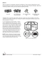
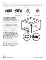
After the entire AnF is assembled, install the Vent-Kit-6x12. These vents are designed to be used 

with the AnF Series as well as universal vents for many other types of fi re pit enclosures. Look at the 

contents provided to ensure you have received everything correctly.

Install the vents on opposite sides of 

the enclosure to ensure cross fl ow 

ventilation. Cross fl ow ventilation is 

necessary to provide free fl owing air to 

assist in keeping the enclosure dry and 

cool during operation of a fi re pit.
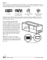
Cut an rectangular opening 9.75”w x 

3.75”h into on opposite sides of the 

enclosure. Center the vent over the cut 

out area ensuring the vent slots are 

clear of any obstruction. Mark the holes 

with a pencil or marker. Drill six 1⁄4” 

pilot holes, position the vent centered 

over the opening, insert a screw into 

the vent and enclosure at the same 

time and secure with washer and nut 

on the inside. Repeat the process until 

all six screws are securing each vent 

into place on both sides of the AnF 

enclosure (See Fig. 31).

9.750”

3.750”

CUT OUT DETAIL

Fig. 31

 Vent Cut Out Dimensions

(2) Vents

(12) Phillips Black 

Pan Head Screw

(12) Stainless Steel 

Nut

(2) Stainless Steel

Flat Washer

NOTE:

 Before cutting the rectangular 

opening for your vents, be sure that 

you are not hitting one of the metal 

studs inside the AnF. The vents must be 

directly across from each other. 

Содержание ANF-L48

Страница 1: ...4 x 18 enclosure fits FPB 24L 30L 36L ANF L66 66 x24 x18 enclosure fits FPB 24L 30L 36L or 2 FPB 24L end to end ANF L74 74 x 24 x18 enclosure fits FPB 24L 30L 36L or 2 FPB 24L or 2 FPB 30L end to end ANF L90 90 x 24 x 18 enclosure FPB 24L 30L 36L or 2 FPB 24L or 2 FPB 30L end to end or 2 FPB 36L end to end ANF S48 42 x 42 x 18 enclosure fits FPB 19R 25R FPB 20S 26S ANF S60 60 x 60 x 18 enclosure f...

Страница 2: ...embly of the AnF should be done at or near the location of the installation Leveling Legs 16 Self Tapping Screws 16 Cement Board Screws AnF R42 AnF R48 4 Legs AnF R60 8 Legs STEP 1 Remove all parts and make sure that you have received all necessary pieces It is important to start the assembly process with the quarter sections upside down To make sure the quarter pieces are upside down the bottom s...

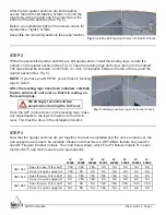
Страница 3: ... models The chart below shows which Fire Pit Burner models fit in each model of AnF and which ones require pan supports Once the AnF is turned over on the leveling legs make any adjustments to the legs to make sure the unit is level This must be done in the installation location After the two quarter sections are butt together secure them with self tapping screws one into the inner hole at the top...

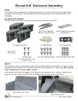
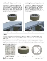
Страница 4: ...rd top See Fig 10 Fig 8 Round MgO Top Fig 9 Round MgO Top Installed Fig 6 Installing 45 Pan Supports Installing 45 Supports Look at the AnF below and note how the pan supports are installed There are two pre drilled holes in the middle of each side at the top on the inside See Fig 6 These holes are used for the 45 pan supports Using the self tapping screws use two screws per pan support and instal...

Страница 5: ... and cool during operation of a fire pit Cut an rectangular opening 9 750 w x 3 750 h into on opposite sides of the enclosure Center the vent over the cut out area ensuring the vent slots are clear of any obstruction Mark the holes with a pencil or marker Drill six 1 4 pilot holes position the vent centered over the opening insert a screw into the vent and enclosure at the same time and secure wit...

Страница 6: ...h panel also has a 90 inner flange on one side See Fig 13 Arrows 2 End Panels Linear AnF Enclosure Assembly Contents of Enclosure Two people are recommended to assemble all enclosures It is also recommended to assemble the AnF enclosure on a flat surface Assembly of the AnF should be done at or near the location of the installation Remove all parts and make sure that you have received all necessary ...

Страница 7: ...l have 8 leveling legs to install Once the unit is turned over on the leveling legs make any adjustments to the legs to make sure the unit is level This must be done on the installation location Butt the inner flange of one of the panels to the non flange side of another panel See Fig 13 After the two ends are butt together secure them with self tapping screws one into the inner hole at the top and ...

Страница 8: ...k on the top of the AnF and attach using the cement board screws provided See Fig 20 Fig 19 Linear MgO Top Fig 20 Linear MgO Top Installed In order to attach the cement board screw securely you must screw them into the metal edges or supports of the AnF Measure 1 inch from the edge of the AnF and drill into the metal through the MgO board You can also drill into the supports that hold the pan in p...

Страница 9: ...opposite sides of the enclosure Center the vent over the cut out area ensuring the vent slots are clear of any obstruction Mark the holes with a pencil or marker Drill six 1 4 pilot holes position the vent centered over the opening insert a screw into the vent and enclosure at the same time and secure with washer and nut on the inside Repeat the process until all six screws are securing each vent ...

Страница 10: ...ommended to assemble the enclosure on a flat surface The assembly of the AnF should be done at or near the location of the installation Remove all parts and make sure that you have received all necessary pieces NOTE It is important to start the assembly process with the panels upside down Ensure the panels are upside down the bottom side has a nutsert See Fig 23 Circle That nutsert needs to be faci...

Страница 11: ...o sections See Fig 25 Before you completely tighten the screws check for squareness Tighten screws Assemble the remaining panels the same manner Fig 24 Butting Ends Together Fig 25 Installing Self Tapping Screws Into Panel While the panels are still upside down install the leveling legs Locate the nutsert on the panels See Fig 11 Take the leveling legs and screw them into the nutsert The legs shou...

Страница 12: ...nF Mark where you need to cut following the template For each piece you will need to cut on the inside in order to fit the burner type Once the pieces are cut place them back on the top of the AnF and attach using the cement board screws provided See Fig 30 Fig 29 Linear MgO Top Fig 30 Linear MgO Top Installed In order to attach the cement board screw securrely you must screw them into the metal e...

Страница 13: ...pposite sides of the enclosure Center the vent over the cut out area ensuring the vent slots are clear of any obstruction Mark the holes with a pencil or marker Drill six 1 4 pilot holes position the vent centered over the opening insert a screw into the vent and enclosure at the same time and secure with washer and nut on the inside Repeat the process until all six screws are securing each vent i...

Страница 14: ...o state Travel diagnostic cost service labor to repair the defect and freight charges on warranty parts to and from the factory will be responsibility of the owner We will not be responsible for labor charges and or damage incurred in installation repair and replacement This Limited Warranty is voided if not assembled installed and operated as intended This Limited Warranty does not cover any defe...

Отзывы: