


1. Field of application
The FINO Micromotor is a brush-free micromotor
suitable for all work in the dental lab or workshop. It
particularly excels in high performance and speed
stability. The control unit can either be used as
table top or knee controlled unit. If used as a tabletop
unit an additional foot switch for speed control can
be installed. The control unit is equipped with seve-
ral safety features to avoid any damage to the hand-
piece. All wearing parts are easily and economically
to replace.
2. Safety precautions
Safe operation and protection of the unit are only
ensured as long as it is used in compliance with spe-
cifications described in the user information using
only permitted tools. Additionally the following must
be observed:
• The directions of the manufacturer if the tools
• Never exceed the maximum allowed speed
of the tool in use
• Always wear eye protection and facemask
• The occupational safety regulations
• The accident prevention regulations
• Never operate the unit with moist hands!
If the safety precautions are not observed the hazard
of injuries for you and people in your surroundings
exists. FINO does not undertake any guarantee in
the case that these safety precautions are not obser-
ved!
3. Commencement of operation
Please check the unit for transportation damages
immediately after unpacking. All transportation
damages must be claimed promptly. Check the vol-
tage given on the type label of the unit and make
sure it corresponds with your mains supply.
3.1 Assembly
3.1.1 Tabletop unit
Danger of stumbling
Install all cables in a way that they do not
cause any occupational hazard. Place the con-
trol unit on an even and dry surface.
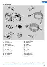
Push the knee-control plate 2
completely in and place the
tabletop stand 3 on the bottom
surface of the control unit.
Sub
sequently screw on the
tabletop stand 3 using the
included two screws. Place the
control unit on your workplace.
Now connect the plug of the
motor cable 5 with the socket 4
on the back of the control unit.
Thereby make sure that the
groove of the socket and the gap of the plug are
opposite each other. Tighten the nut firmly. Now you
connect the plug of the foot switch 7 with the socket
6. Also here the groove of the socket and the gap of
the plug must be opposite each other. Finally you
connect the power supply cable 9 with the power
supply socket 8. Put the control unit on the therefore
selected place on your workplace. Before you con-
nect the power plug with the mains socket check
again whether all cables are firmly connected to the
control unit.
3.1.2 Knee-control unit
Use only the included screws for
the fitting of the attachment
bracket. The use of other screws
could result in the damage of the
unit or your workbench.
We recommend in
stalling the
attachment bracket 10 in a height
of approx. 520-580 mm depen-
ding on your body height. Mark
the holes with a pencil.
Make sure that the attachment
bracket 10 is kept horizontally. If
necessary use a water level. Drill
the holes with a thin drill. Screw
the screws completely in to
ensure a frictionless installation
of the control unit.
3
ENU


