background image

MEGA SD - Cod.197DD8100

GB

GENERAL INFORMATION

INDEX

DECLARATION OF CONFORMITY .................................2
GENERAL INFORMATION ...............................................3
OVERALL DIMENSIONS .................................................4
SAFETY INDICATIONS ....................................................6
INSTALLATION ................................................................8
TEChNICAL FEATuRES ............................................... 11
START-uP AND OPERATION ........................................12
MAINTENANCE .............................................................36
TROubLE ShOOTING ..................................................40
wIRING DIAGRAM ........................................................41

OUTFIT

The following accessories are supplied with the compressor:

•  use and maintenance manual 

•  electric box panel key  

•  oil/condensate exhaust tube

Check  that  the  above  accessories  are  available.  Once  the  goods  have  been  delivered  and  accepted,  no  complaints  are 

accepted.

CONDITION OF THE MACHINE WHEN SUPPLIED

Every compressor is shop tested and delivered ready to be installed and to be set at work. 

Oil used is: ROTENERGY PLuS.

Содержание MEGA SD 50

Страница 1: ...n onderhoudshandleiding Instruction and maintenance manual manual de uso y mantenimiento manual de uso e manutenção Bruks och underhållsanvisning Руководство по эксплуатации и обслуживанию Instrukcja użytkowania i konserwacji ÏÄÇÃÉÅÓ ÑÇÓÇÓ ÊÁÉ ÓÕÍÔÇÑÇÓÇÓ MEGA SD Cod 197DD8100 Rev 0 01 2012 MEGA SD 50 60 75 GB ...

Страница 2: ...umo direktyvų 2006 42 ES 2000 14 ES 2006 95 ES 2004 108 ES 2009 105 ES EN 1012 1 EN 60204 1 EN 60335 1 EN 61000 6 3 4 N Erklærer under eget ansvar at luftkompressoren her beskrevet er i overensstemmelse med sikkerhetsforskriftene i direktivene 2006 42 EC 2000 14 EC 2006 95 EC 2004 108 EC 2009 105 EC EN 1012 1 EN 60204 1 EN 60335 1 EN 61000 6 3 4 LV Apliecinā zem savas pilnīgas atbildības ka apakšā...

Страница 3: ...0 wiring diagram 41 OUTFIT The following accessories are supplied with the compressor use and maintenance manual electric box panel key oil condensate exhaust tube Check that the above accessories are available Once the goods have been delivered and accepted no complaints are accepted CONDITION OF THE MACHINE WHEN SUPPLIED Every compressor is shop tested and delivered ready to be installed and to ...

Страница 4: ... 1560 840 950 150 70 1590 6 2 5 150 70 1 6 3 93 MEGA SD Cod 197DD8100 GB OVERALL DIMENSIONS ...

Страница 5: ... 950 150 1590 660 660 150 150 70 160 510 150 70 161 200 723 260 MEGA SD Cod 197DD8100 GB OVERALL DIMENSIONS ...

Страница 6: ...specialised technician Warning symbols Prohibition symbols High temperature risk Electric shock risk Risk from hot or dangerous gases in the work area Pressurised container Moving mechanical parts Maintenance in progress Machine with automatic start up Do not open hatches when the machine is functioning If necessary always use the emergency stop button and not the line isolating switch Do not use ...

Страница 7: ...uring compressor operation and stay hot for a certain time after compressor stops Do not position inflammable close to and onto the compressor Do not move the compressor when the tank is under pressure Do not operate the compressor if the power cable is damaged or defective or if connection is unstable Do not operate the compressor in wet or dusty environments Never aim the air jet at people or an...

Страница 8: ... 1 6 9 8 12 1 5 1 11 7 8 13 15 14 10 10 3 2 4 MEGA SD Cod 197DD8100 GB installaTION DESCRIPTION OF THE COMPRESSOR ...

Страница 9: ...and move the machine to the room chosen for its location with maximum care Keep all packing materials at least for the warranty period for possible moving In case of need it will be safer for delivery to the technical assistance dept Then dispose of packing materials in compliance with current laws LOCATION fig 2 The room chosen for the installation of the compressor should meet the following requ...

Страница 10: ...should be at least at 1 7 m from the ground The switch A should be easily reached by the operator The cables should be of the approved type and installed with the following grade of protection minimum IP44 N B To determine the cables cross section and the type of switch refer to the data reported on the technical table Sizing according to VDE 0100 Part 430 and 523 star delta starter 30 C ambient t...

Страница 11: ...197DD8100 GB TECHNICAL FEATURES Technical characteristics Working pressure Air end F a d according ISO 1217 annex C Oil quantity Oil quantity for topping upmains Max final air temperature above ambient Re claimable heat Fan flow rate Oil carry over Electric motor Rated power Max power absorbed ventilation included Electrical box protection class Maximum ambient temperature Noise level according Pn...

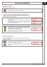
Страница 12: ...rection of rotation of the motor The direction of rotation must be that indicated by the adhesive labels located to the side of the screw unit see picture Note that even a few seconds of incorrect rotation may cause serious damage A phase sequence checking device to prevent mistakes is fitted in the electrical panel Before starting the machine read the following sections and the chapter on mainten...

Страница 13: ... daily weekly have been enabled this key can be used to disable compressor functioning priority control It does not operate at emergency level K3 RESET button Makes it possible to reset compressor fault messages after eliminating the causes of these As the faults can be displayed only in the main screen page the RESET key is effective only during display of this During parameter modification opera...

Страница 14: ...ted the first time the key is pressed without performing any other function Indicator setting LED L1 Voltage presence LED yellow Must always be ON when the compressor is powered L2 Warning LED yellow This LED switches on to indicate critical conditions or a minor fault that does not block the compressor this indication may refer to the need for maintenance or irregular operating conditions Switchi...

Страница 15: ...ndication of network pressure LINE 2 indication of compression temperature of air oil mixture LINE 3 messages about operating conditions LINE 4 hour and date information menu access tree menu access quick language change message To change the language use the K5 and K6 keys If the compressor is operating LINE 1 and LINE 2 always show the above information Particular indications error messages addi...

Страница 16: ...n the display shows Load run the intake valve is open and the machine operates at full load produces the nominal capacity of compressed air During functioning delivery pressure increases once the preset maximum line pressure threshold value has been reached the control system sets the compressor to idling by closing the intake valve Unload run When the pressure drops below the preset minimum thres...

Страница 17: ... compressor vents the pressure inside the separator reservoir preparing for subsequent restart If the K1 START key is pressed again before the preset timed restart time has passed a new timing is shown on display D1 which indicates the time to compressor restart This function prevents restarting the compressor when it is still pressurized avoiding electrical motor overload Compressor emergency STO...

Страница 18: ...d date information menu access tree menu access quick language change message To change the language use the K5 and K6 keys After 60 seconds from pressing of the fast key the display is set to a Iow level of brightness The first time a key is pressed excluding the K1 START K2 STOP K3 RESET control keys high level brightness of the display is restored while subsequent pressing of the keys produces ...

Страница 19: ...agraph 4 2 4 Indicates the total hours of operation of the compressor ref paragraph 4 2 2 Indicates the total hours of operation of the compressor at full load ref paragraph 4 2 2 Indicates the time remaining to initial maintenance any other maintenance operations to be carried out within 100 hours from initial maintenance are also displayed cyclically ref paragraph 4 2 2 It provides the informati...

Страница 20: ... the structured menu used to carry out all compressor control and programming operations The options and setting in the various menu can be ref paragraph 4 2 2 ref paragraph 4 2 3 ref paragraph 4 2 4 visible only if theCAN BUS interface has been instalied ref paragraph 41 5 ref paragraph 4 2 6 ref paragraph 4 2 7 ref paragraph 4 2 1 ref paragraph 4 2 8 Pressure XX X bar psi Temperature XXX C F Rea...

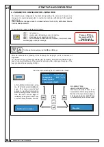
Страница 21: ...s pressed the password entered expires after five minutes with possibly display of a re entry prompt PASSWORD ENTER PASSWORD ENTER PASSWORD 0000 CONFIRMED pressing the K9 ENTER key CANCELLED pressing the K4 ESC key Each time a parameter is modified the factory set default value can be restored for the selected compressor pressing the K3 RESET key 4 2 1 PASSWORD menu Used to enter a password to ena...

Страница 22: ... for air filter xxx hrs Time remaining for oil filter xxx hrs Time remaining for other components Replacement made for air filter Replacement made for oil filter Replacement made for other components Operating time Total xxx hrs Operating time load xxx hrs only with access enabled Confirm replacement air filter OK Confirm replacement oil filter OK Confirm replacement other components OK M AINTENAN...

Страница 23: ... to set the measurement units for pressure and temperature Date time Used to set the current date and time The time and date are entered using the K7 and K8 keys to modify the flashing values the K5 and K6 keys to move to modification of the previous next character After entry of the values these can be confirmed with the K9 ENTER key or cancelled with the K4 ESC key Display settings Makes it poss...

Страница 24: ...Language Measur unit Display setting Display setting Operating mode See next page Select language v ENGLISH Select language OTHER LANGUAGES Pressure unit Unit bar temperature unit Unit Cels Set date and time hh mm day dd mm yyyy Contrast Intensity xxx Lighting ON Brightness xxx Lighting OFF Brightness xxx Operating mode AUTOMATIC Operating mode CONTINUOUS ...

Страница 25: ... only if the CAN BUS interface been installed Compress control v LOCAL Compress control REMOTE Compress control PROGRAM Compress control V CONTINUOS Compress control VNETWORK CONTINUOS DRYEN v enable in ON DRYEN Disable Type remote contr ON OFF Type remote contr LOAD UNLOAD Type remote contr ON OFF load unload AUTORESTART v Disable AUTORESTART enable onlyonmachinesequipped with integrated dryer on...

Страница 26: ... factory setting that most frequently used which makes it possible to exploit the control logic of the compressor using the pressure signal measured locally by the machine LOAD UNLOAD is the setting that makes it possible to control full load and unload operation with an external control logic in this case the pressure signal measured by the compressor is ignored for the purposes of operating meth...

Страница 27: ...re zero or very Iow it is usually necessary to increase the pressure to the minimum working value as quickly as possible With the PREFILL function enabled the compressor participates in system prefilling bypassing the global control functions in this phase The compressors involved in this operation are started quickly in sequence thus avoiding any overlap of the start up phases of two or more mach...

Страница 28: ...ecks network pressure to establish whether another compressor must be started T OFF When the control system deactivates a compressor following an increase in network pressure the T OFF timer is started at the end of this count the system checks network pressure to establish whether another compressor is to be deactivated 4 2 5 OPERAT PARAMETERS menu This menu is used to make the configuration sett...

Страница 29: ... to start again when network pressure has dropped below the minimum threshold value This parameter is effective only if operating mode has been set to AUTOMATIC see paragraph 4 2 3 This parameter must be optimized according to the consumption trend of the network and its accumulation capacity In the case of Iow consumption and if it is seen that the compressor remains inactive for long periods mot...

Страница 30: ...he control unit will keep the compressor running during the change over at midnight from one day to the next Weekly programming Weekly programming makes it possible to set different start stop cycles for each day of the week up to a maximum of three per day The following rules apply Non programmed cycles identified by the five hyphens that replace the time are not effective Cycles for which the st...

Страница 31: ...o the PROGRAMMING menu from submenus PROGRAMMING Reset programm Programming mode Daily programming Weekly programming Confirm RESET programming OK Programming mode v Daily Modo programmaz v Weekly Every day Start 1 Every day Start 1 other days other cycles Monday Start 1 Monday Start 1 other days other cycles ...

Страница 32: ...diagnostic TEST comply with all the safety rules WARNING When carrying out the test certain parts of the machine are powered control coils and rotating parts are activated motor compressor fari The operator must therefore take a l the necessary precautions during these checks Error messages The control unit saves all the faults that have occurred and which have caused stoppage of the machine alarm...

Страница 33: ...OSTICS DIAGNOSTIC Test ERROR MESSAGES Run diagnostic Test OK DIAGNOSTIC Test TEST digit INPUTS INPUT n 1 status Emergency OK other inputs DIAGNOSTIC test TEST digit OUTPUTS OUTPUT n 1 active Line other OUTPUTS DIAGNOSTIC Test Rot direction test Press for test Press if OK Press ESC if NEGAT Last error message other error messages ...

Страница 34: ... the controller permits continuous monitoring of machine operating conditions and prompt indication of the need far maintenance operations or of any malfunctions The indications are divided into two categories Warning messages These messages may refer to scheduled maintenance operations critical operating conditions or minor faults which do not block the compressor but which must be checked in ord...

Страница 35: ...he machine to RESET first of ali eliminate the fault at this point LED L3 starts to flash indicating that reseti can be carned out pressing the RESET key All faults that cause blocking of the compressor are saved in a error message log file refer to paragraph 4 2 7 The following faults block the machine EMERGENCY STOP compress block Compression temp too high block Ambient temperature too Iow block...

Страница 36: ...particular the power electric connection screws 3 Visually check that all fittings seal properly 4 Check the belt tension and if necessary reset it 5 Check the hours of work and the type of service selected 6 Check room temperature BEFORE MAINTAINING THE MACHINE ALWAYS PERFORM THE FOLLOWING Press the machine automatic stop button do not use the emergency button Power the machine off by means of th...

Страница 37: ...gainst the light for the presence of splits in this case replace filters The filtering elements and the cover must be assembled carefully so as not to allow the passage of dust into the compressor unit Never allow the compressor to function without the filtering element Cleaning the radiator It is recommended that in case of over temperature anomalies and however at least once a year that the radi...

Страница 38: ...er Maintenance Checking the transmission belt tension fig 10 When the compressor is stopped remove the panel C e the panel D and check the belt tension Use a suitable measuring instrument that determines with precision the belt tension degree by means of a frequency measuring device in order to perform this control Operate as follows Place the microphone of the measuring instrument near to the bel...

Страница 39: ...D8100 GB REPLACING THE MINIMUM VALVE Fig 11 Replace the seals highlighted with the letter G CLEAN AIR PREFILTER FIG 12 Remove the prefilter from its seat Wash it with soapy water solution dry it completely before restarting the machine ...

Страница 40: ...rty Regulator open It cannot open because no command is received Oil separator filter clogged Min pressure valve does not close perfectly Voltage too low Tube leaking Remedy Check voltage press Reset and then restart Check motor absorption and relay setting In case of regular absorption press Reset and restart Check oil drain hose and check valve Check oil level and drain some if necessary Replace...

Страница 41: ...230 400 Sec 0 24 220 VA 150 VA 250 VA 220 VA 220 VA TC2 Transformer Pr 0 230 400 Sec 0 12 SB Emergency button n 2 NC 230V 10A FU1 FU2 FU3 Ceramic fuses 6 3 x 32 GF 2A 500V FU4 Ceramic fuses 6 3 x 32 GF 4A 500V 8 A 6 A 10 A 8 A 8 A FU5 FU6 Ceramic fuses 6 3 x 32 GF 1A 500V KM1 Coil line hour counter 24 24 V 50 60 Hz 37 KW 22 KW 45 KW 30 KW 37 KW KM2 Coil triangle hour counter 24 V 50 60 Hz 37 KW 22...

Отзывы: