11
7. GAS CYLINDER AND GAS PRESSURE
REGULATOR CONNECTIONS
Only for MIG welding:
Skip this charter
entirely if the welder is to be used for MMA
Carefully follow the procedure shown
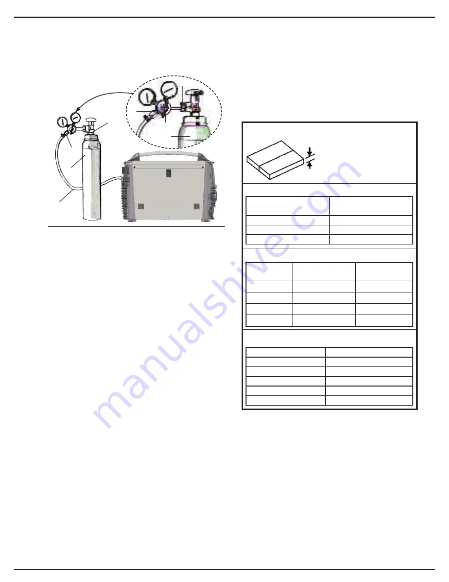
in Fig. 6:
Connect the pressure regulator (2) to the gas
cylinder (3). Tighten the bolt (6) between the reg-
ulator (2) and the cylinder (3). Do not overtighten
to avoid damaging the cylinder valve (1).
Connect the gas hose of the torch (4) to the
pressare regulator (2) and clamp securely
using a clasp (5). (Alternatively use cylinder
and hose fast connectors).
Connect the other end of the gas hose (6) to the
socket on the rear panel of the welder unit
(Fig.2 – 23), securing it with a clasp.
Connect the gas hose from the torch to the
appropriate socket (7) on the front panel of the
unit (fig 1 - 33), tightening clockwise. Do not
over-tighten.
Open the gas cylinder valve (1). Press the torch
button and check that gas is flowing through
correctly.
WARNING:
Cylinders contain high pressure
gas. Handle them with care. Inappropriate
treatment can cause serious accidents. Do not
pile gas cylinders up and never expose them to
excessive heat, flames or sparks. Do not bang
cylinders against each other. Contact your sup-
plier for more information regarding the use and
maintenance of gas cylinders.
WARNING:
Never use cylinders that are dam-
aged or show signs of oil or grease leakage.
Contact your supplier immediately of any such
circumstances.
8. WELDING METHODS
8.1 Manual MIG welding
To select this mode, turn knob 7 (Fig.1) to the
MIG MAN setting.
N.B.:
These are guidelines only and are to be con-
sidered applicable solely to workpieces no thicker
than 4mm. The settings are selected according to
wire diameter, location and welding gas.
Fig 7:
Current reference values, wire diameter,
wire speed and electronic inductance.
Proceed as follows for manual MIG welding:
1.
Set the welding current, according to the
thickness of the workpiece and the diameter of
the wire to be used, using the knob 10, Figure 1
(Step 1, Fig8). The display panel (Fig. 1 – 1)
shows the value selected.
2.
According to the diameter of the wire, set
the wire speed using knob 9 of Figure 1.
(Step 3, Fig.8)
3.
According to the kind of material, regulate the
electronic inductance (Fig. 1 – 8). (Step 4, Fig8)
4
3
2
1
6
2
5
1
3
5
Fig.6
Step 1:
Current selection
Convert the thickness of the
workpiece in to Amperes (A)
using the following formula:
0.025mm = 1A
i.e. 3mm = 125A
Step 2:
Wire diameter selection
Step 3:
Wire diameter selection
AMPERE (Min-Max)
WIRE DIAMETER
40-90 A
0,6mm
60-140A
0,8mm
80-160A
1mm
100-200A
1,2mm
wire diameter
recommended
wire speed
wire speed
0,6mm
1 amp ( 90mm/min) 90x120=11m/min
0,8mm
1 amp ( 50mm/min) 50x120=6m/min
1mm
1 amp ( 40mm/min) 40x120=5m/min
1,2mm
1 amp ( 30mm/min) 30x120=3,5m/min
Step 4:
Electronic inductance selection
Material
Electronic inductance setting
Ferrous materials (SG2 SG3)
min <~> med
Stainless steel (NI-Cr)
med
Aluminium (Al)
med <~> max
Copper-silicon (Cu-SI3)
med <~> max
Copper-aluminium (CU-Al8)
med <~> max
Содержание TM 215
Страница 1: ...Instructionsmanual TM215 ...
Страница 3: ......
Страница 4: ...1 6 5 A 2 2 2 5 V 1 4 0 A 2 5 6 V 1 2 0 A 2 4 9 V 3 1 1 V 1 7 2 V 2 0 5 V 1 3 0 A ...
Страница 6: ......
Страница 11: ......
Страница 12: ......
Страница 13: ......
Страница 14: ......
Страница 15: ......
Страница 16: ......
Страница 19: ......
Страница 24: ... NOTE ...
Страница 25: ... NOTE ...
Страница 26: ... NOTE ...
Страница 28: ......


