


________________________________________________________________________________________________________________
12-20-2002
Figure Sheet 1-853-A
Page 2
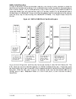
SBPC-21-EN/IP Switch/Jumper Configuration
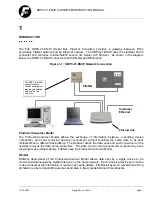
Since the SBPC-21-EN/IP participates in two networks at the same time, it must have two network
addresses (a FifeNet address and an Ethernet IP address). The FifeNet address is set via the FifeNet
serial port that is common with many FifeNet peripherals. The Ethernet IP address is programmable
by dip switches or via the Ethernet connection. See the dip switch description and IP address
configuration setup shown below for more information. If the SBPC-21-EN/IP is installed as the end
point in a FifeNet network, all four jumpers described below should be installed.
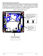
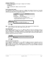
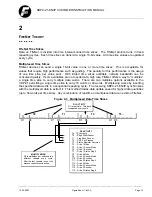
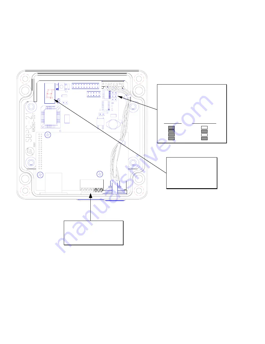
Figure 1-2: SBPC-21-EN/IP Top View
These jumpers should be installed if the
SBPC-21-EN/IP is at the end of a
FifeNet network. They provide network
termination. The other two jumpers
should always be installed as they
select half-duplex FifeNet
communication.
Terminated Not
Terminated
The 7-segment LED is
used to display errors or
exceptions. During normal
operation, the display will
continuously “cycle” the
outer segments.
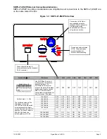
Ethernet IP address configuration
switches. See the following page
for description of these switches.