


________________________________________________________________________________________________________________
12-20-2002
Figure Sheet 1-853-A
Page 29
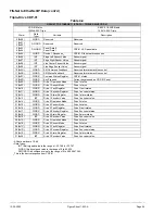
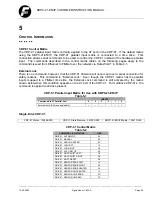
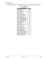
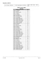
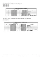
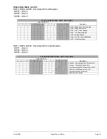
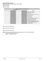
Status Data Block
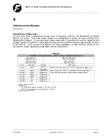
For reference, the CDP-01 Status Data Blocks are listed in the tables on the following pages.
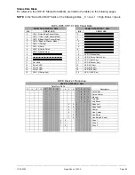
NOTE
: In the “Data Word Bit #” fields on the following tables: _ 0 = Low, 1 = High, Blank = Ignore
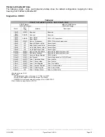
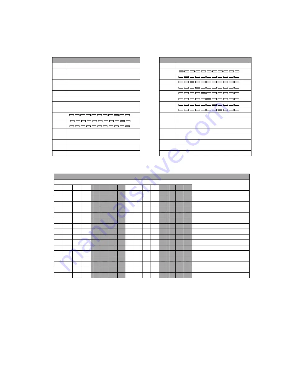
DW4, DW5: CDP-01 LED Panel Data
PANEL DATA WORD 0: DW4
PANEL DATA WORD 1: DW5
Bit
CDP-01 LED
Bit
CDP-01 LED
0
LED 12 (Line Edge Sensor Mode
0
1
LED 11 (Line Center Sensor Mode)
1
2
LED 10 (Edge Right Sensor Mode)
2
3
LED 9 (Edge Left Sensor Mode)
3
4
LED 17 (Polarity)
4
5
LED 16 (Gain)
5
6
LED 15 (Guide Point)
6
7
LED 14 (Auto Setup)
7
8
8
LED 3 (Manual Key)
9
9
LED 2 (Servo-Center Key)
10
10
LED 1 (Auto Key)
11
Not Used
11
LED 8 (Sensor Key)
12
Drive 3 LED
12
LED 4 (f1 Key)
13
Drive 2 LED
13
LED 5 (F2 Key)
14
Drive 1 LED
14
LED 6 (F3 Key)
15
LED 13 (Setup Key)
15
LED 7 (ASC Key)
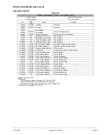
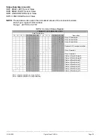
DW6: Device 1 Response
DEVICE 1 RESPONSE: DW6
Data Word Bit No.
15 14 13 12 11 10 9
8
7 6 5 4 3
2
1
0
Description
0
0
0
Automatic
0
0
1
Servo-Center
0
1
0
Manual
0
1
1
Jog Plus
1
0
1
Jog Minus
0 0 0
Edge Left
0 0 1
Edge Right
0 1 0
Center
0 1 1
Line Center
1 0 0
Line Edge
1 0 1
Line Edge & Center
0 0
Drive 1
0 1
Drive 2
1 0
Drive 3


