Creating the site map
Page 88
FiberPatrol IDS Software Guide
Defining the Zone Boundaries (Zone Definitions)
1.
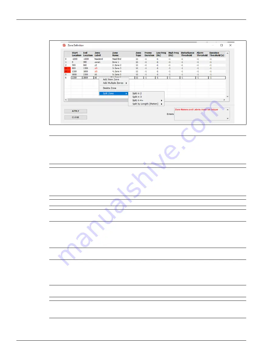
In the Manage menu, select Zone Definition.
2.
In the Zone Definition window, enter the average Start and End location of each zone from the
Location/calibration table that was recorded during the tap testing, beginning with Zone 1.
3.
Keep the Zone Labels in ascending order, and with the same nomenclature as used in the
default configuration (i.e., zone1, zone2, zone3, etc.).
4.
Change the Zone Names as required.
5.
Once complete, select Apply, and then select Replace.
Figure 107 Zone Definition window
Note
Right-click a Zone line to add or delete a Zone.
When a new zone is added, the Start Location and End Location are 0,
the Zone Label is newzone and the zone name is New Zone.
All zones must be assigned unique Zone Labels and Zone Names,
including disabled zones.
Note
The end location of one Zone boundary must be the same as the start
location for the next Zone boundary (i.e., if Zone 1 ends at 100 m, then
Zone 2 begins at 100 m).
For a fully closed perimeter, the end point location of the final Zone must
be the same as the start point location for the first Zone.
Note
The FiberPatrol FP1150 sensor supports up to1440 distinct alarm zones.
Note
The Zone Definition dialog includes error checking to prevent errors in
setting up the detection zones.
Note
Do not change the Head End zone, the Zone Type, Frame Duration, Filter
settings (Low Freq, High Freq), Thresholds, or Display mode at this time.
Note
Zone Names must begin with a number for use with the Network
Manager software (e.g, 7: West Fence, 8: West Gate).
Note
Assign meaningful Zone Names, as the Zone Names are displayed
during alarm activity and are recorded in the Event Log (e.g., for Zone
Label zone3 enter Zone Name 3: Main Gate).


