8
Technical data
Cordless drill/screwdriver C 12
Motor voltage
12 V
Idle-running speed
1. Speed
0 - 450 rpm
2. Speed
0 - 1500 rpm
Max torque
Soft boring (wood)
18 Nm
Hard boring (metal)
30 Nm
Adjustable torque
1. Speed
2 - 7 Nm
2. Speed
0.5 - 2.5 Nm
Chuck capacity
1.5 - 13 mm
Max. drill diameter for wood
25 mm
Max. drill diameter for metal
14 mm
Tool fi tting in chuck
1/4“
Weight without battery pack
0.96 kg
Charger
LC
45
Supply voltage (input)
230 - 240 V~
Line frequency
50/60 Hz
Charging voltage (output)
7.2 - 18 V=
Charging current
3 A
Quick charge
max. 3 A
Compensation charge pulsating
NiCd 1.3 Ah
app. 30 min
NiCd 2.4 Ah
app. 50 min
NiMH 3.0 Ah
app. 70 min
Battery pack
BPS 12 C NiCd
BPS 12 S NiCd
BPS 12 S NiMH
Order number
493 348
492 268
491 821
Voltage
12 V
12 V
12 V
Capacity
1.3 Ah
2.4 Ah
3.0 Ah
Temp. range for charging
5 - 45 °C
5 - 45 °C
5 - 45 °C
Temperature monitoring
u s i n g N T C r e s i s t o r
Weight
0.56kg
0.73 kg
0.75 kg
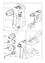
The specifi ed illustrations can be found at the beginning of the operating instructions.
1
Before starting up, please observe
the following
1.1
Intended use
Cordless drills are suitable for drilling metal,
wood, plastics and similar materials, as well as
tightening and screwing in screws (into wood,
up to a diameter of 6 mm).
The LC 45 battery charger is designed for re-
charging the battery pack listed.
The user is liable for damage and injury
resulting from incorrect usage!
1.2
Safety instructions
Before using the machine, read the
enclosed safety instructions and these
operating instructions carefully and
thoroughly.
Save all enclosed documents and pass the ma-
chine with all these documents only.
1.3
Noise and vibration information
Cordless drill/screwdriver
The typical values determined in accordance
with EN 60745 are:
Sound pressure level
65 dB(A)
Sound-power level
76 dB(A)
Measuring uncertainty allowance
K = 4 dB
Measured acceleration
<2.5 m/s²
The noise level can exceed 85 dB(A)
during operation.
Wear
ear
protection!
1.4
Wall mounting LC 45
The charger LC 45 has two longitudinal slots on
its rear by which it can be suspended on walls
using two screws (e.g. button-headed or fl at
head screw with a shaft diameter of 5 mm).
Screw both screws into the wall 96 mm apart
until the screwhead is protruding from the wall
by approx. 4 mm.
2
Machine settings
Remove the battery pack before any adjust-
ments, maintenance or repair is carried out!
2.1
Exchanging the battery pack
Removing battery pack
Press the two buttons (1.1) and slide the bat-
tery pack forwards to remove.
Inserting battery pack
Slide the battery pack into the holder on the
underside of the handle until it latches into
place (see Fig. 1).
Seen at Ideal Tools.
Содержание C 12
Страница 3: ...Seen at Ideal Tools ...


