9
2.2
To change the direction of rotati-
on
The selector button (1.4) determines the direc-
tion of rotation.
Turn button from right to left =
clockwise ro-
tation.
Turn button from left to right =
antic-
lockwise rotation.
Selector button in central
position =
circuit interlock.
2.3
Shifting speeds
Change only when completely stop-
ped!
Using the shift lever (1.5), the speed can be
changed.
1. Speed:
Lever forward - Figure 1 is visible.
2. Speed:
Lever backwards - Figure 2 is vi-
sible.
2.4
Torque adjustment
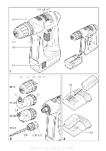
By turning the adjustment ring (1.6) the re-
quired torque can be adjusted. The arrow (1.7)
aligns with the adjusted state.
The machine switches off when the set torque
has been reached. The machine does not start
running again until the ON/OFF switch (1.3) is
released and then pressed again.
Drilling
Drilling symbol on adjustment ring aligns with
the arrow = maximum torque.
Screws
Torque corresponding to setting:
Position 1 = low torque
Position 20 = high torque
3
Tool holding fi xture, attachments
3.1
Chuck BF-FX
The chuck is used to clamp drills and bits.
a)
Fitting/removing the chuck
Fitting
-
Place the chuck on the drill spindle (2.5)
and twist until the hexagon key (2.4) of the
chuck latches into the hexagon socket of the
drill spindle.
-
Pull the unlocking ring (2.3) forwards,
press the chuck onto the drill spindle up to
the stop and release the unlocking ring.
Removal
- Pull the unlocking ring forwards and remove
the chuck.
b)
Changing tools
- Turn the clamping sleeve (2.2) anti-clockwise
to open the clamping jaws (2.1) (
Note:
the
spindle is automatically locked when the ma-
chine is switched off).
-
Insert the tool into the chuck.
- Clamp the tool by turning the clamping sleeve
clockwise. Always make sure that the tool is
clamped centrally in the chuck.
3.2
Angle attachment DD-AS
The angle attachment permits work (drilling,
screwing) vertical to the machine’s longitudinal
axis.
a)
Fitting/removing the angle attach-
ment
Fitting
- Place the angle attachment on the drill spindle
and turn until it catches in the desired position
(
Note:
The angle attachment can be fi tted in
16 different angle settings).
- Lock the angle attachment by turning the
fastening ring (2.7) tightly clockwise.
Removal
- Turn the fastening ring anti-clockwise up to
the stop and remove the angel attachment.
b)
Fitting/removal of chuck on angle
attachment
The chuck is fi tted on the shaft (2.6) of the
angle attachment in the same way as on the
drill spindle of the machine.
3.3
Eccentric attachment DD-ES
The eccentric attachment is used to hold bits.
It allows screwing close to edges.
a)
Fitting/removing the eccentric at-
tachment
The eccentric attachment is fi tted/removed in
the same was as the angle attachment (see
Chapter 3.2).
b)
Changing tools
- Pull the unlocking ring (2.8) back and remove
the tool and/or insert the new tool.
3.4 CENTROTEC
WH-CE
toolholder
The CENTROTEC toolholder enables rapid chan-
ges of tools with CENTROTEC shafts.
Do
not
fi t CENTROTEC tools at the round
shaft section in a conventional chuck to
prevent damage to the shaft.
Danger of injury!
When changing
tools, handle the tool and its sharp
cutters with special care and wear pro-
tective gloves, if necessary.
a) Fitting/removing
CENTROTEC
Fitting
- Pull the release ring (2.11) forwards, place
the toolholder as far as it will go on the drill
spindle (2.5) and let go of the release ring.
Removal
- Pull the release ring forwards and take off the
toolholder.
b) Changing
tools
- To insert or remove a tool with CENTROTEC
shaft, pull the green release ring (2.10) back.
On inserting the tool, turn it until its hex shank
arbour (2.9) locks in place in the hexagonal
shank of the drill spindle, and push the tool
into the toolholder as far as it will go.
3.5
Tool holding fixture in the drill
spindle
Bits can be fi tted directly in the hexagon socket
holder of the drill spindle (2.5) to make the
machine lighter and shorter.
Seen at Ideal Tools.
Содержание C 12
Страница 3: ...Seen at Ideal Tools ...


