


02.07.04
FTE
MS-Word Dokument
Index: .
Änd-Nr.:
Anz.:
Tag:
Name:
Copyright by Festo AG & Co.
All rights reserved.
Referred to protection notice ISO 16016
.
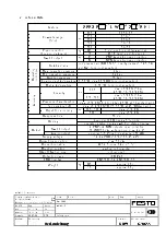
Typ
SFE3-
TE-BST
Tag
Name
Werkstoff
gez.
23.03.04
jhz
gesehen
08.06.04
udm
Freigabe
Gefertigt aus:
Bl-Nr: 19 / 20
Maßstab:
Benennung:
Dok-Art:
Teile-Nummer:
Bed.Anleitung
DRW
678655
©
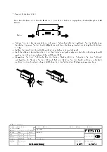
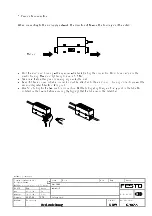
These key functions apply when setting switching mode, reference
value and zero point.
back to flow rate
display.
Rückschaltpunkt/Sp. max
switch output ON (manual)
output Out1 ON
output Out2 ON
setting data for switch output function
retrieve data
UP
read value
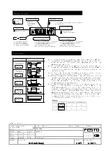
standard key functions
change value with UP/DOWN
change mode
using
UP/DOWN keys
Hold down
flashing
flashing
release
For safety reasons, the
flow rate display will
reappear if the key is not
pressed for more than 2
seconds.
If the key is not
pressed for long
enough, the flow rate
display reappears,
store
press
once
switching point
Out2 setup
switching point
Out1 setup
store switching point Out1
actuation point/sp.min
reference-value
display
reference-value
display
DOWN
press
display Out1
LED symbol for
operating mode
flashing
press once
press
once
press once
display
change
display
change
press
once
press
once
back to flow rate
display.
press once
hold down
hold down
press once
store
back to flow rate displ.
flashing
press
once
press once
press
display
change
store switching point
Out2
see switching point
Out1
reset point/sp.max
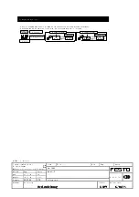
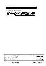
If keys are pressed while the flow rate is being displayed, switch-on and switch –off points as well as the LED symbols can be displayed and
confirmed. Switching function is not affected by the following operating procedures:
display
Out1 settings
an eigen
hold down
hold down
display
Out2 settings
operating-mode display reference value display
display reference value OFF operating-mode display
ON-side
flashing
OFF-side
flashing
Operating procedure for switch output function and manual output operation
Checking the settings


