


02.07.04
FTE
MS-Word Dokument
Index: .
Änd-Nr.:
Anz.:
Tag:
Name:
Copyright by Festo AG & Co.
All rights reserved.
Referred to protection notice ISO 16016
.
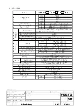
Typ
SFE3-
TE-BST
Tag
Name
Werkstoff
gez.
23.03.04
jhz
gesehen
08.06.04
udm
Freigabe
Gefertigt aus:
Bl-Nr: 11 / 20
Maßstab:
Benennung:
Dok-Art:
Teile-Nummer:
Bed.Anleitung
DRW
678655
©
OPERATING INSTRUCTIONS
MINIATURE FLOW SENSOR
SFE3 series
N
Please read these operating instructions carefully before using this product. Special attention
should be paid to the section containing the safety information.
N
Keep these instructions for later reference.
1
.
ATTENTION:
F
This device may not be used for metering in public supply facilities.
The device does not fulfil the conditions required for the purpose of invoicing. The device must
be used solely for industrial purposes.
G
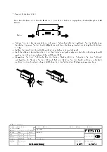
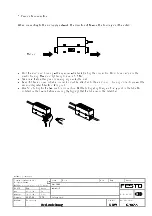
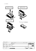
During installation, the device housing must be securely affixed to prevent the housing and the
connecting lines from being damaged.
H
The device must only be used in conjunction with the flowing media listed as suitable under
Technical Data. When used in conjunction with any other media, device performance and safety
cannot be guaranteed. The device must never be used with corrosive gases, flammable gases,
oxygen etc.
I
Compressed air from a compressor supply contains condensed water, petroleum oxides, foreign
matter and other contaminants. Therefore, a filter, an air drier and an oil-vapour filter should be
attached to the primary side of the sensor (inlet side).
J
If the device is being used for suction or other vacuum applications, an air filter must be attached
to the suction side to prevent foreign matter from being sucked in.
N
This device is designed for air, dry compressed air as well as N
2
. Do not use this device in
conjunction with corrosive or flammable gases.
N
Do not touch electrical connections (open conducting parts): electric shocks can be fatal. The
power supply must be deactivated during connection. Conducting parts must never be touched
with bare hands.
N
Use only power supply units that guarantee reliable electrical isolation of the operating voltages
with at least 4kV isolation resistance to IEC 742/EN 60741/VDE 0551 ( Protected Extra-Low
Voltage, PELV). Switch power packs are permitted, providing they guarantee reliable isolation to
EN 60950 / VDE 0805.
Safety information
!


