


02.07.04
FTE
MS-Word Dokument
Index: .
Änd-Nr.:
Anz.:
Tag:
Name:
Copyright by Festo AG & Co.
All rights reserved.
Referred to protection notice ISO 16016
.
Typ
SFE3-
TE-BST
Tag
Name
Werkstoff
gez.
23.03.04
jhz
gesehen
08.06.04
udm
Freigabe
Gefertigt aus:
Bl-Nr: 18 / 20
Maßstab:
Benennung:
Dok-Art:
Teile-Nummer:
Bed.Anleitung
DRW
678655
©
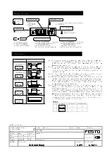
key
key
key
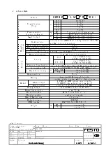
N
display shows
flow rate, switching
settings and
device status
3-digit LED display
overflow LED
switching status display
(
OUT1, OUT2)
operating mode LED
: flow rate display
in standard mode (setup deactivated)
:
min / max storage
lighted display
:
permanent
:
flashing
:
switching output ON
:
overcurrent protection activated
:
value
at position 4
N
activate setup mode
N
change setup mode
N
return to flow rate display
N
stop peak value storage
N
flow rate display active =
sequential display of Out 2 settings
N
peak value storage mode active =
display of peak value
N
mode selection = select mode
N
data setting = increase value etc.
N
flow rate display active =
sequential display of Out 1 settings
N
peak value storage mode active =
display of peak value
N
mode selection = select mode
N
data setting = increase value etc.
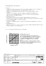
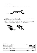
Window comparator 1
(closer, normally open)
Window comparator 2
(opener, normally closed)
Threshold value comparator
1
(opener, normally closed)
Threshold value comparator
2
(closer, normally open)
Stop
Hy 1% FS
min 3 % FS
Hy 1%FS
F.S
0
switching point min
switching point max
flow
ON
OFF
Hy 1 % FS
min. 3 % FS
Hy 1% FS
hysteresis min. 1 % FS
ON
OFF
ON
OFF
Output is switched off regardless of
switching points
ON
OFF
0
flow
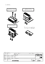
flow rate
0
switching point min
switching point max
flow
0
reset point
actuation point
flow
0
reset point
actuation point
flow
hysteresis min. 1 % FS
ON
OFF
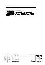
Out
LED symbol
actuation point
reset point
1
200
350
2
300
250
Display and operation
Switching operation modes
Note 1: During continuous operation, there should be an interval of at least 3 % of the
measuring range’s final value between two switching points. A hysteresis of 1 %
of the measuring range’s final value (FS) is automatically added to the ON and
OFF switching points.
Note 2: During threshold value operation, there should be an interval of at least 1 % of
the measuring range’s final value (FS) between two switching points. If both
switching points are identical, no switching operation is initiated or the operation
is unstable.
Note 3: The left-hand side of the circuit symbol corresponds to a low flow rate, the
right-hand side to a high flow rate.
Note 4: The sensor’s switching characteristics may be unstable if, e.g., the pressure of
the medium fluctuates. Stable switching characteristics must be ensured. This
requires either the determination of a sufficient interval between the two
switching points or employing the sensor in an area without pressure fluctuation.
Note 5: The ratio between actuation and reset point is determined during the setting of
the operation mode. A reversal of the ratio is impossible. Implementing the set
switching characteristics has priority for this device. The ratio is automatically
determined when the two switching points are entered. Both values are assigned
and processed in a pre-determined manner as the actuation and reset point. In
other words: even if the two switching points are entered in reverse order, the
allocation is carried out correctly and the operating mode corresponds to
specifications.
Example


