6
Assembly
6.1
Safety
WARNING
Risk of Injury due to Unexpected Movement of Components
For vertical or slanted mounting position: when power is off, moving parts can
travel or fall uncontrolled into the lower end position.
• Bring moving parts of the product into a safe end position or secure them
against falling.
WARNING
Risk of injury due to unexpected movement of components.
The drive can move freely in the voltage-free state. This can cause unexpected
movements of the connected mechanics and crush parts of the body.
• Bring moving parts of the mechanical system into a safe position.
6.2
Unpacking
1. Open packaging.
2. Remove all transport materials (e.g. foils, caps, cardboard boxes).
3. Remove the product from the packaging and place it on the mounting surface.
4. Dispose of packaging and transport materials.
6.3
Mounting the cylinder
Requirement
–
No collision in the range of motion of the attachment component with mounting
components.
–
Flat mounting surface maximum 0.2 mm over the stroke length of the bearing
surface.
–
No distortion or bending when installing the product.
1. Select mounting attachments
2. Place the mounting attachments on the support points.
3. Tighten retaining screws.
Observe the maximum tightening torque and maximum screw-in depth.
For additional information, contact your local Festo Service.
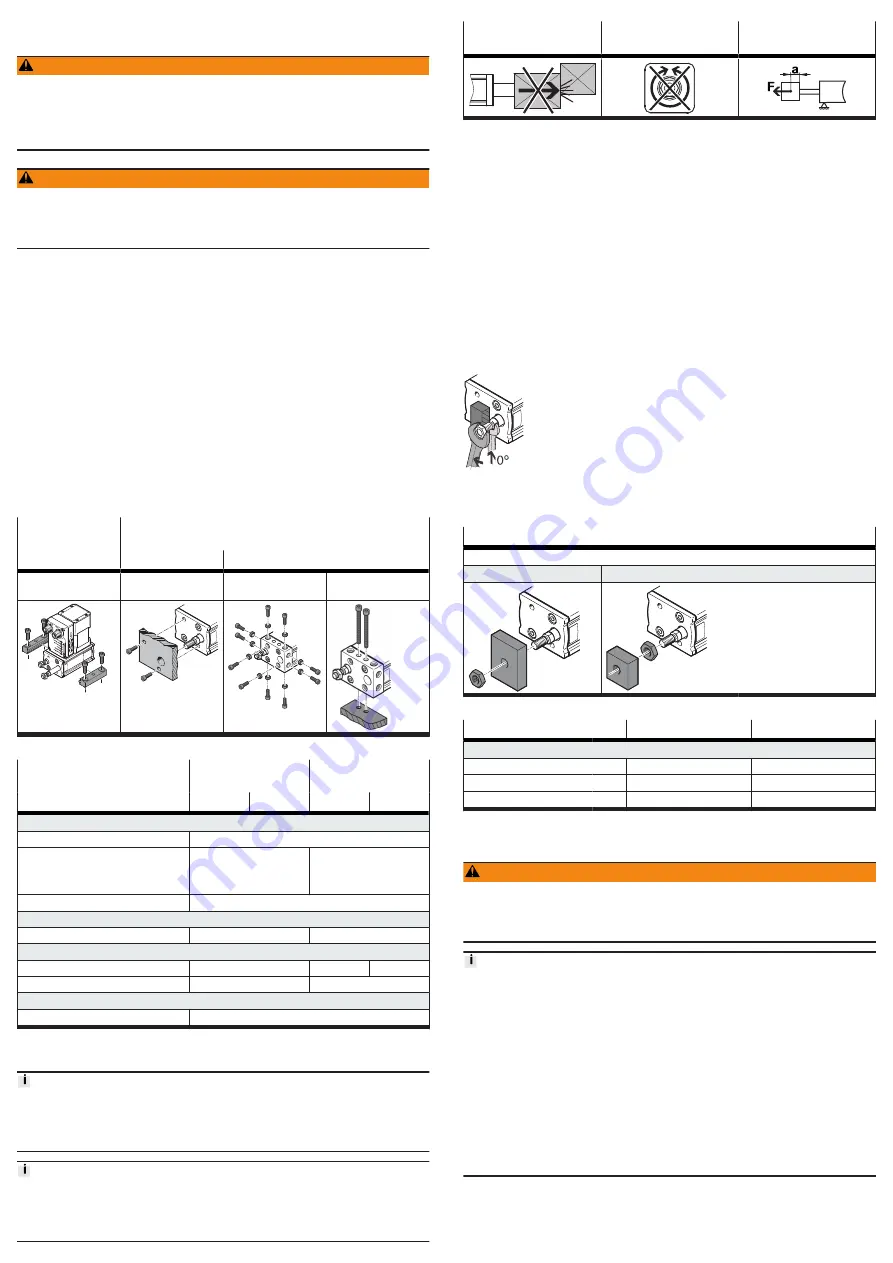
Profile mounting
EAHF-L2
Direct fastening
EPCE, standard
EPCE-...-MB/-MD/-MF, Multimount
Mounting via profile
groove
Mounting via thread
Mounting via thread
Mounting via through-
hole
Tab. 2: Overview of mounting components
EPCE, standard
EPCE-...-MB/-MD/-
MF, Multimount
Size
45
60
45
60
Direct fastening via thread
Screw
M4
Max. screw-in depth t
max
[mm]
front, rear
15
14
top, bottom, left, right
–
8
Max. tightening torque
[Nm]
2.9
Centring (bore tolerance H7)
Centring sleeve
[mm]
–
Æ
7
Direct fastening via through-hole
Hole length
[mm]
–
34.6
38.6
Hole diameter
[mm]
–
4.5
Profile mounting EAHF-L2
Screw
Tab. 3: Information on mounting attachments
6.4
Mounting the attachment component
Torque on the Piston Rod
During commissioning and operation, the piston rod may only be operated
without torque.
If external torques occur, an external guide must be used.
Mounting the attachment component on the piston rod
When mounting the attachment component do not exceed the max. torque of the
piston rod. The max. torque of the piston rod may only be used for a short time
during mounting
Tab. 6 Information on attachment components.
Collision-free
Torque-free
Centre of gravity and
tilting moment
Tab. 4: Requirement for attachment component
Requirement
–
No collision in the range of motion of the attachment component with mounting
components.
–
No transverse load or torque on the piston rod.
Absorb external forces and torques via an external guide.
–
Position of the centre of gravity and tilting moment (force F parallel to the axis
of movement) of the attachment component centred and close to the piston rod
(short lever arm a).
1. Select accessories
2. Screw the lock nut onto the male thread of the piston rod or attachment
component.
3. Rotate or place the attachment component on the piston rod.
4. Tighten lock nut.
The tightening torque must not act on the piston rod. Counterhold with a
suitable tool on the spanner flat of the piston rod.
Observe maximum tightening torque. The piston rod must not be turned.
Fig. 4: Torque-free mounting
When using an additional external guide, ensure that the electric cylinder and
piston rod are parallel and aligned exactly.
Direct fastening
Mounting via male thread
With nut
With lock nut
–
Rod eye SGS
–
Rod clevis SG
–
Coupling piece KSG
–
Self-aligning rod coupler FK
Tab. 5: Overview of attachment component
Size
45
60
Piston rod
Width across flats
ß
[mm]
7
10
Max. torque on the piston rod [Nm]
0.5
1
Nut, lock nut
M6
M10x1.25
Tab. 6: Information on attachment components
7
Installation
WARNING
Risk of injury due to electric shock.
• For the electrical power supply with extra-low voltages, use only PELV circuits
that guarantee a reinforced isolation from the mains network.
• Observe IEC 60204-1/EN 60204-1.
Damage to the device due to non-approved potentials at the pins
• Power connection:
• Do not connect pin 3
• Logic connection:
• EMCS-ST is not hot-pluggable. Only after connection of the reference poten-
tials GND/L– [Pin 4/8] can 24 V levels be applied to digital outputs DO1/DO2
[Pin 2/3] or the IO-Link communication signal C/Q [Pin 3].
• The DO1/DO2 [Pin 2/3] digital outputs and the IO-Link C/Q [Pin 3] communi-
cation signal must be disconnected 100 ms before the power supply connec-
tions GND/L– [Pin 4/8] and 24 V DC/L + [Pin 1], e.g. by the interposition of
relay contacts.
• GND and L– connections:
• The Power, GND [Pin 2] and Logic, GND/L– [Pin 4/8] connections must have
the same potential.
1. Connect cables to the [Logic] and [Power] connections of the integrated drive
EMCS-ST.
2. Connect cables to the controller or IO-Link master and to the PELV fixed power
supply units.


