


WARNING
Risk of Injury due to Unexpected Movement of Components
For vertical or slanted mounting position: when power is off, moving parts can
travel or fall uncontrolled into the lower end position.
• Bring moving parts of the product into a safe end position or secure them
against falling.
WARNING
Risk of injury due to unexpected movement of components.
• Protect the positioning range from unwanted intervention.
• Keep foreign objects out of the positioning range.
• Perform commissioning with low dynamic response.
Malfunction
Possible cause
Remedy
Loud running noises,
vibrations or rough
running of the axis.
Coupling distance too
short.
Observe permissible coupling spacings
è
Instruction manual for motor mounting kit,
Torsional stresses
–
Install axis without tension. Make sure that
the contact surface is flat
–
Change the layout of the attachment compo-
nent (e.g. payload).
–
Align axes parallel to each another.
Current controller set-
tings.
Optimise controller data (e.g. velocity, accelera-
tion, ...).
Resonance oscillation
of the axis.
Change the travel velocity.
Wear on bearing or
guide.
–
Contact local Festo Service.
–
Toothed belt wear.
–
Contact local Festo Service.
–
Replace toothed belt
Insufficient lubrication
of guide.
Lubricate the guide
Vibrations at the canti-
lever.
Operation at the reso-
nant frequency of the
axis.
–
Change the travel velocity.
–
Change the acceleration.
–
Increase axis stiffness (e.g. shorter support
distances).
–
Change the payload geometry.
Long cantilever oscilla-
tion.
Resonant frequency of
profile and payload too
low.
–
Change the payload geometry.
Cantilever or slide
does not move.
Coupling slips.
Check the mounting of the shaft-hub connection
è
Instruction manual for the motor mounting
kit,
Loads too high.
Reduce forces and torques. Consider dynamics.
Toothed belt torn.
–
Contact local Festo Service.
–
Overruns the end posi-
tion.
Sensor does not
switch.
Check sensor, installation and parameterisation.
Idling torque too high.
Wear in the drivetrain.
–
Contact local Festo Service.
–
Toothed belt skips.
Toothed belt preten-
sioning too low.
–
Contact local Festo Service.
–
Current controller set-
tings.
Optimise controller data (e.g. velocity, accelera-
tion, ...).
Loads too high.
Reduce travel speed.
Wave formation on the
cover strip or alumi-
nium abrasion on the
axis.
Wear on belt reversals.
–
Retension cover strip
–
Replace belt reversal and cover strip
Clamping unit does not
open.
Operating pressure too
low.
Increase operating pressure to the permissible
pressure range.
Clamping unit leaks.
–
Contact local Festo Service.
–
Holding force is not
reached.
Clamping component
worn or clamping
mechanism defective.
–
Contact local Festo Service.
–
Tab. 12: Overview of fault clearance
11
Disassembly
WARNING
Unexpected movement of components.
Injury due to impacts or crushing.
• Before working on the product, switch off the control and secure it to prevent it
from being switched back on accidentally.
WARNING
Risk of Injury due to Unexpected Movement of Components
For vertical or slanted mounting position: when power is off, moving parts can
travel or fall uncontrolled into the lower end position.
• Bring moving parts of the product into a safe end position or secure them
against falling.
1. Disconnect electrical installations.
2. Remove the mounted attachment component.
3. Remove the attached accessories.
4. Remove motor and mounting kit.
5. Remove the mounting attachments.
6. Observe transport information
12
Technical data
12.1
Technical data, mechanical
Use the Festo sizing software for sizing the drive
Cantilever axis ELCC-TB-60/70/90/110
Size
60
70
90
110
Design
Electromechanical axis with toothed belt
Guide
Recirculating ball bearing guide
Mounting position
any
Max. feed force Fx
[N]
300
600
1200
2500
Max. driving torque
[Nm]
5.2
10.4
33
90
Max. no-load drive torque at v = 0.2 m/s [Nm]
0.6
1.2
2.5
4
Max. velocity
[m/s]
5
Max. acceleration
[m/s
2
]
50
30
Repetition accuracy
[mm]
±
0.05
Feed constant
[mm/rev]
96
96
160
216
Ambient temperature
[°C]
–10 … +60
Storage temperature
[°C]
–20 … +80
Degree of protection
IP20
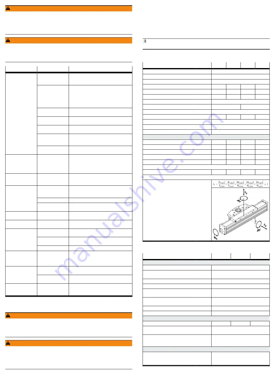
Max. permissible forces and torques on the slide
Fy
[N]
4200
9600
13900
20600
Fz
[N]
4100
9400
13500
20000
Mx
[Nm]
35
105
165
315
My
[Nm]
290
825
1300
2365
Mz
[Nm]
285
795
1230
2285
Distance to guide centre
a
[mm]
29.9
39.1
43.8
54
Calculating the load comparison factor
fv
Tab. 13: General data, ELCC-TB
Clamping unit ELCC-...-C
Size
70
90
110
Clamping unit
Design
clamping unit integrated in the drive
Clamping type
Clamping by spring force, releasing by com-
pressed air
Effective direction
both ends
Well-tried component
in accordance with EN ISO 13849-1:2015
Permissible operating pressure for
releasing the clamping unit
[bar]
4 … 6.5
Operating medium
Compressed air in accordance with ISO
8573-1:2010 [7:4:4]
Response time
[ms]
.
100
Ambient temperature
[°C]
–10 … +60
Clamping
1)
Static holding force
[N]
450
550
850
Max. axial movement caused by
clamping of the clamping unit
[mm]
0.2
Service-life value B10 with load
2)
[million
switching
cycles]
0.05
Emergency braking
3)
Max. number of emergency braking
operations
1000
with energy per emergency braking
[J]
30
1) Clamping means that the clamping unit fixes the stationary cantilever at its current position.
2) The general assumption B10d = 2 x B10 is not permissible.
3) Emergency braking means braking of the moving mass, e.g. in case of power failure of the system.
Tab. 14: Technical data for clamping unit ELCC-...-C