


6.3
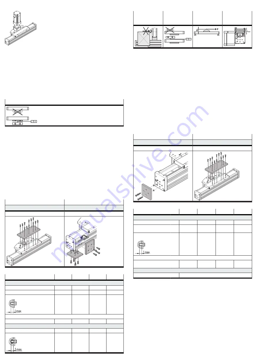
Mounting the motor
Fig. 3: Mounting the motor (example: axial mounting from above)
Only loosen screws or threaded pins that are described in the directions in the
instruction manual.
1. Select the motor and motor mounting kit from
Festo
When using other motors: observe the critical limits for forces, torques and
velocities.
2. Fasten motor mounting kit, observe instructions
3. Fasten the motor without tension. Support large and heavy motors.
Connect motor cables only on completion of mounting.
6.4
Mounting the axis
Flatness
Tab. 2: Requirement for attachment component
Requirement
–
No collision in the movement space of the attachment component with motor,
mounting and sensor components.
–
Sufficient space to reach maintenance interfaces.
–
Sufficient space for accessing and mounting the clamping unit or sealing air
connection.
–
Flatness t of the mounting surface of the mounting component of 0.01 mm over
the slide surface.
–
No distortion or bending when installing the product.
1. Select mounting attachments
2. Slide operation: position the mounting attachments on the support points.
3. Tighten retaining screws.
Observe max. tightening torque and max. screw-in depth.
In the case of planar and 3-dimensional gantries, pay attention to parallelism,
product height and alignment of the axes.
For additional information, contact your local Festo Service.
Cantilever operation
Slide operation
Direct fastening on slide
Slot nut NST for mounting slot
Mounting via thread
Mounting via profile groove
Tab. 3: Overview of mounting components
Size
60
70
90
110
Direct fastening on slide
Screw
M5
M5
M6
M6
Max. tightening torque
[Nm]
6
6
10
24
Max. screw-in depth t
max
[mm]
10
10
12
16.2
Centring (bore tolerance H7)
Centring element
[mm]
Æ
5
Æ
9
Æ
9
Æ
12
Slot nut NST
Screw
M5
M5
M6
M6
Max. screw-in depth t
max
[mm]
6
6
12
12
Tab. 4: Information for mounting components
6.5
Mounting the attachment component
Collision-free
Flatness
Centre of gravity
and tilting
moment
Max. screw-in
depth
Tab. 5: Requirement for attachment component
Requirement
–
No collision in the movement space of the attachment component with motor,
mounting and sensor components.
–
Flatness t of the mounting surface of the attachment component of 0.01 mm
above the slide surface.
–
Position of the centre of gravity and tilting moment (force F parallel to the axis
of motion) of the attachment component centrally on the slide and close to the
slide surface (short lever arm a).
–
The maximum screw-in depth of the retaining screws is not exceeded.
1. Select accessories
2. Mounting position of the attachment component:
–
Cantilever operation: position on end cap or place on profile.
–
Slide operation: position on slide. Centring elements are placed in centring
holes in delivery status.
3. Tighten retaining screws.
Observe max. tightening torque and max. screw-in depth.
When using an additional external guide, ensure exact parallelism and alignment
of the axes and guide.
Recommendation: use guide mountings with tolerance compensation.
Cantilever operation
Slide operation
Direct fastening on end cap
Direct fastening on slide
Mounting via thread
Mounting via thread
Tab. 6: Overview of attachment component
Size
60
70
90
110
Direct fastening on end cap
Screw (inside/outside)
M4
M4/M5/M6
M6/M8
M6/M8
Max. tightening torque
(inside/outside)
[Nm]
3
3/6/10
10/18
10/18
Max. screw-in depth t
max
(inside/outside)
[mm] 14
14/15/18
18
18
Centring (bore tolerance H7)
Centring element
(inside/outside)
[mm]
Æ
7
Æ
7/
Æ
9
Æ
9
Æ
9
Direct fastening on slide
Screw
Tab. 7: Information on attachment component
6.6
Mounting accessories
Mounting sensor and shock absorber
Requirement
–
No collision in the movement space of the attachment component with motor,
mounting and sensor components.
–
Protection against uncontrolled overtravel of the end positions.
–
Referencing to reference switch or end position.
–
Query of end positions or intermediate positions.
–
Avoidance of hard impacts at the end positions.
1. Select accessories
2. Mount mechanical end position protection:
–
Mount the shock absorber stop
–
Mount shock absorber retainer
–
Mount the shock absorber
3. Mount the sensor (reference or query):