


9.2
Checking axis elements
Checking toothed belt wear
The pretension of the toothed belt is designed for the entire service life.
Tensioning of the toothed belt is not permitted.
1. ELCC-...-PU1:
–
Initial check: after 1000 km.
–
Periodic check: every 500 km.
ELCC-...-PU2:
–
Initial check: after 5000 km.
–
Periodic check: every 1000 km.
2. If there is visible wear on the toothed belt: send the axis to Festo or contact
www.festo.comFesto Service.
Checking the cover strip (ELCC-...-70/90/110-P9 only)
•
Check: every 2000 km.
If waves form, the cover strip must be retensioned.
1
2
3
4
Fig. 6: Retensioning cover strip
1
Clamping element
2
Cover strip
3
Screw
4
End cap
Retensioning cover strip on both sides
1. Loosen screws
3
.
2. Push cover strip
2
into the end cap
4
.
3. Tighten cover strip with a clamping element
1
.
4. Tighten the screws.
Tightening torque: 6 Nm ±10 %.
If it is no longer possible to retighten the cover strip, the belt reversals and the
cover strip should be replaced
Clamping element
Checking clamping unit (ELCC-...-70/90/110-C only)
Check the holding force of the clamping unit at every maintenance interval or after
every emergency braking in the event of a power failure.
–
Check holding function as follows:
1. Move the cantilever or slide to an end position.
2. Exhaust the clamping unit connection
3. Allow the test force (the test pressure) to act on the drive for at least 5 s.
During this time, the cantilever or the slide must not move.
The test force and the tolerance window can be taken from the risk assess-
ment of the application.
The clamping unit must be replaced after 1000 emergency braking operations or
after 50,000 clamping operations
è
Contact your local Festo service centre.
9.3
Cleaning
Clean the product with a soft cloth. Do not use aggressive cleaning agents.
Removing abraded particles in the drive head
At every maintenance interval remove the particles from the toothed belt and
cover strip wear on the axis or in the drive head as required.
2. With the interlocks (1) pressed, pull the housing (2) off the drive head.
9.4
Lubrication
Lubrication interval and accessories
NOTICE
The lubrication interval S
int
is dependent on the load acting on the product.
Load factors include e. g.:
• Dusty and dirty environment
• Nominal stroke
>
2000 mm or
<
300 mm
• Speed
>
2 m/s
• Ambient temperature
>
+40 °C
• Service age of product
>
3 years
• Travel profile matches triangular operation (frequent acceleration and braking)
If one of these factors applies:
• Halve lubrication interval S
int
.
If several factors apply at the same time:
• Divide service interval S
int
by four.
Lubrication
Recirculating ball bearing
guide KF
Guide rail
Lubrication interval
–
Calculate the comparative
loading factor f
v
using the
formula for combined loads
–
Lubrication intervals S
int
as a
function of the load comparison
factor f
v
can be taken from the
diagram.
As required, e.g. if the grease layer
is insufficient.
Lubrication point
Lubrication hole
Interface
Lubricant
–
ELCC-TB-KF: roller bearing grease
LUB-KC1
–
ELCC-TB-KF-F1: Elkalub VP 874,
Chemie-Technik, Vöhringen
–
ELCC-TB-KF: roller bearing grease
LUB-KC1
Grease gun
Pressure grease gun with pinpoint nozzle LUB-1, 647958
–
Lubrication adapter, axial output,
LUB-1-TR-I, 647959
–
Lubrication adapter, radial
output, LUB-1-TR-L, 647960
–
Tab. 10: Overview of lubrication intervals and accessories
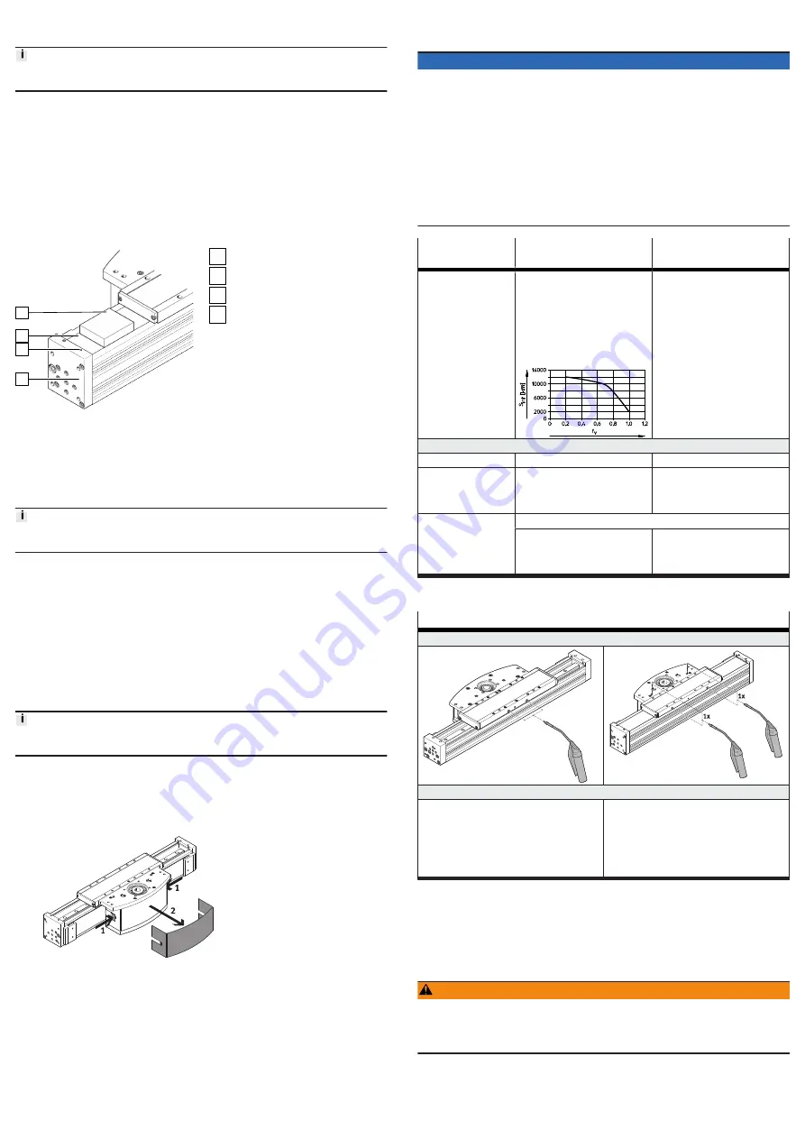
Lubricating guide
Recirculating ball bearing guide KF
Lubrication holes
Grease quantity per lubricating hole:
ELCC-TB-60 (size), 2 lubrication holes, inject
the specified weight of grease into both lubri-
cation holes at the front.
–
60: 1.7 g
ELCC-TB-70/90/110 (size), 4 lubrication holes,
inject the specified weight of grease into the
left and right of only one lubrication hole at the
front or top.
–
70: 5 g
–
90: 7.5 g
–
110: 11.2 g
Tab. 11: Lubrication overview
1. Inject lubricant into two lubrication holes.
2. During the lubrication process, travel the entire traverse path to distribute the
lubricant evenly inside the machine.
10
Malfunctions
10.1
Fault clearance
WARNING
Unexpected movement of components.
Injury due to impacts or crushing.
• Before working on the product, switch off the control and secure it to prevent it
from being switched back on accidentally.