


–
Mount sensor bracket and sensor.
–
Align and fasten the switch lug.
–
Fasten cable.
4. Mount the slot cover.
Instruction manuals
Shock absorber retainer and shock
absorber stop DAYP-E21
Sensor bracket and switch lug DASI-
E21
–
Shock absorber retainer: mounting via profile
groove
–
Shock absorber stop: mounting on the drive
head
–
Switch lug: mounting via profile groove
–
Sensor bracket: mounting on the drive head
Instruction manual
–
Protect the sensor from external magnetic or
ferritic influences (e.g. min. 10 mm distance
to slot nuts).
–
Preferably use hardware limit switches with
normally closed function (protection guaran-
teed even in case of sensor failure).
–
Query switching lug only with inductive
sensor.
Instruction manual
Tab. 8: Overview of shock absorber and sensor mounting
Connecting sealing air or clamping unit
The supply ports of the axis can be used as follows, depending on the product
variant:
–
Sealing air connection: for axes with strip cover ELCC-...-70/90/110-P9.
–
Clamping unit connection: for axes with attached clamping unit
ELCC-...-70/90/110-C.
The use of sealing air at approx. ± 0.02 MPa (± 2.9 psi; ± 0.2 bar) reduces or
prevents subsequent contamination:
–
The application of negative pressure minimises the release of abraded particles
into the environment.
–
Applying overpressure reduces the penetration of dirt into the drivetrain.
Always use Loctite 222 to seal an open supply port.
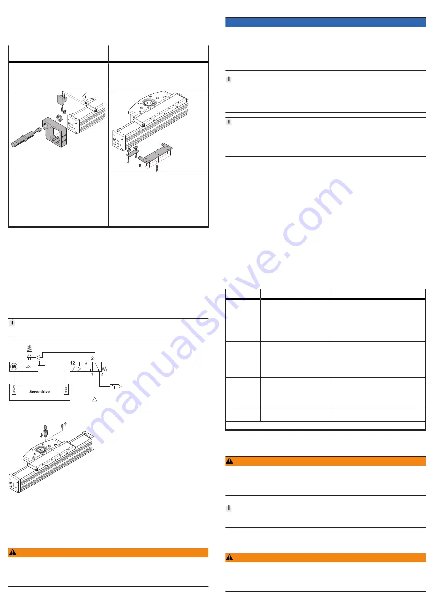
Fig. 4: Example of control of clamping unit ELCC-...-C
Fig. 5: Connecting sealing air or clamping unit
1. Remove one plug screw from the threaded hole of the slide or drive head.
2. Mount the fitting (M5; 0.5 Nm) and connect the tubing.
7
Commissioning
7.1
Safety
WARNING
Risk of injury due to unexpected movement of components.
• Protect the positioning range from unwanted intervention.
• Keep foreign objects out of the positioning range.
• Perform commissioning with low dynamic response.
7.2
Performing commissioning
NOTICE
Elasticity of the toothed belt
The elasticity of the toothed belt generates an additional spring effect at high
acceleration and deceleration, which can lead to an inadmissible nominal/actual
deviation when the slide is moved or when the end position is reached.
• Consider the setpoint deviation determined during the test run during parame-
terisation of position setpoint values.
When the motor is removed, the motor encoder loses its absolute reference to the
reference mark (e.g. by turning the motor drive shaft).
• Carry out a homing run after every motor mounting in order to establish the
absolute reference between the motor encoder and the reference mark.
Running noises during operation
Identically constructed axes can generate different running noises depending on
the parameterisation, mode of operation, type of mounting, installation environ-
ment and components.
Requirement:
–
Mounting of the drive system checked.
–
The protective cover of the cover strip is removed.
–
Installation and wiring of the motor checked.
–
No foreign objects in the movement space of the drive system.
–
Max. permissible feed force and drive torque not exceeded as a function of
acceleration, deceleration (e.g. stop function, quick stop), velocity, moving
mass and mounting position.
–
No mechanical overload of the axis and dynamic setpoint deviation not
exceeded (e.g. overrunning the end position) due to force and torque peaks
or overshoot effects.
Limit overloads and overruns by jerk limitation, lower acceleration and deceler-
ation setpoints or optimised controller settings.
–
Control and homing travel at reduced velocity, acceleration and deceleration
setpoint values.
–
No test run to mechanical end stops.
–
Software end positions do not lie within the effective range of the mechanical
stops.
Steps
Purpose
Note
1. Check travel
Determining the direction of
travel of the cantilever or slide
–
The direction of movement of the cantilever
or slide for positive and negative position
values depends on the mounting position
of the motor on the axis.
–
Set a required reversal of direction of rota-
tion via parameters in the servo drive or
controller.
2. Homing
Determination of the reference
point and adjustment of the
dimensional reference system
–
during the initial start-up pro-
cedure
–
after replacement of the motor
Permissible reference points:
–
towards reference switch.
Travel at reduced velocity
Further information
è
Instruction manual of
the drive system,
3. Test run
Checking the operating condi-
tions
Check application requirements:
–
Cantilever or slide runs through the com-
plete travel cycle in the specified time.
–
Cantilever or slide stops moving when a
limit switch is reached.
4. Test
clamping unit
Testing the holding force
After a successful test run, the drive system is ready for operation.
Tab. 9: Commissioning steps
8
Operation
WARNING
Risk of injury due to unexpected movement of components.
• Protect the positioning range from unwanted intervention.
• Keep foreign objects out of the positioning range.
• Perform commissioning with low dynamic response.
Test the holding function of the clamping unit after every emergency braking in
the event of a power failure
9
Maintenance
9.1
Safety
WARNING
Unexpected movement of components.
Injury due to impacts or crushing.
• Before working on the product, switch off the control and secure it to prevent it
from being switched back on accidentally.