Use the product only as follows:
–
Use only in an industrial environment. Outside industrial environments,
e.g. in commercial and residential/mixed-use areas, it may be necessary to
take measures to suppress radio interference.
–
Use only in combination with modules and components that are permissible
for the respective product variant
è
–
Only use the product if it is in perfect technical condition.
–
Only use the product in original status without unauthorised modifications.
Only the conversions or modifications described in this and the further applic-
able documents are permitted.
2.3
Training of Qualified Personnel
Installation, commissioning, maintenance and disassembly should only be con-
ducted by qualified personnel. The qualified personnel must be familiar with
installation of electrical control systems.
3
Further information
–
Accessories
è
–
Spare parts
è
4
Service
Contact your regional Festo contact person if you have technical questions
è
5
Product overview
5.1
Function
The product acts as a participant in an EtherNet/IP or Modbus TCP network,
establishing a connection between a higher-order controller and the modules in
an automation system CPX-E.
Web server
The integrated web server provides read access to the key parameters and dia-
gnostic functions of the automation system CPX-E. The web server can be
accessed by entering the IP address in the address bar of a web browser.
Factory settings of the bus module:
IP address: 192.168.1.1, subnet mask: 255.255.255.0 (DHCP = active)
5.2
Configuration
5.2.1
Product Design
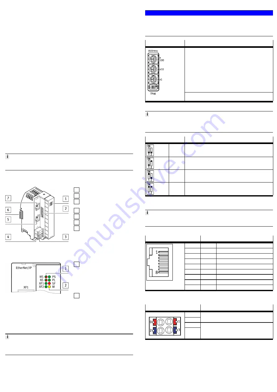
1 LED displays
2 Rotary and DIL switches
3 Terminal strip for operating
voltage supply U
EL/SEN
[XD]
4 Terminal strip interlock
5 Network connection [XF2]
6 Linking element
7 Network connection [XF1]
Fig. 1 Product design
5.2.2
Display Components
1 Network-specific LED displays:
– Module status [MS] (green, red,
orange)
– Network status [NS] (green, red,
orange)
– Connection/data traffic
[XF1]/[XF2] (green)
2 System-specific LED displays:
– Operating voltage supply
U
EL/SEN
[PS] (green)
– Load voltage supply U
OUT
[PL]
(green)
– System error [SF] (rot)
– Force mode [M] (yellow)
Fig. 2 LED displays
The network-specific LED displays are described below
è
The system-specific LED displays are described in the documents for the automa-
tion system CPX-E
è
5.2.3
Control Elements
NOTICE!
Damage to internal electronics.
Damage to at-risk components due to electrostatic discharge.
•
Ensure your body is electrostatically discharged before activating the rotary
switch.
Rotary/DIL switches
Function
The 3 rotary switches are used to set the 4th octet of the IP address
(192.168.1.XXX).
Possible Settings:
–
0 = Dynamic addressing via DHCP/BOOTP
–
1 … 255 = permissible address range
Valid Values:
–
EtherNet/IP: 300 … 555 (IP address = value – 300)
–
Modbus TCP: 600 … 855 (IP address = value – 600)
–
Factory setting: 900
In the case of invalid values, the IP parameters are reset to dynamic
addressing (DHCP).
The diagnostic mode is set using the DIL switches
è
Tab. 5 Rotary/DIL Switches
For switch positions 0 … 255, the protocols EtherNet/IP and Modbus TCP can be
used in parallel. The rights to control the outputs are assigned to the protocol that
sends outputs first.
DIL switch
Function
DIL 1: OFF
DIL 2: OFF
No diagnostics
1)
DIL 1: OFF
DIL 2: ON
Status bits activated
DIL 1: ON
DIL 2: OFF
I/O diagnostic interface activated
DIL 1: ON
DIL 2: ON
Reserved
1) Factory setting
Tab. 6 DIL Switch
Changes to the rotary and DIL switches only take effect following a restart of the
bus module.
5.2.4
Connecting Elements
Connection [XF1], [XF2]
Signal
1
TD+
Transmitted data +
2
TD–
Transmitted data –
3
RD+
Received data +
4
n.c.
–
5
n.c.
–
6
RD–
Received data –
7
n.c.
–
8
n.c.
–
1)
Shield
Functional earth
1) Housing
Tab. 7 Connection [XF1], [XF2]
Port [XD]
1)
Signal
0
1
+24 V DC operating voltage supply U
EL/SEN
2
3
0 V DC operating voltage supply U
EL/SEN
1) The ports XD.0 and XD.1 and also XD.2 and XD.3, respectively, are interconnected in the terminal strip.
Tab. 8 Port [XD]
6
Transport and storage
•
Observe specifications for environmental and storage conditions
è
Tab. 17 Ambient Conditions UL/CSA.
7
Assembly
•
Assemble the module as outlined in the “Instruction manual for Automation
system CPX-E”
è


