8
Installation
8.1
Network
•
Use cables as described in the cable specification
è
è
Tab. 17 Ambient Conditions UL/CSA.
8.2
Operating Power Supply U
EL/SEN
1. Please note the information in the “Instruction manual for Automation system
CPX-E”
è
2. Make sure that the power supply is switched off.
3. Connect the lines to the terminal strip in accordance with the “Instruction
manual for Automation system CPX-E”
è
9
Commissioning
NOTICE!
Malfunction due to switching on the higher-order controller and automation
system CPX-E in the incorrect order.
•
Switch on the higher-order controller and automation system CPX-E according
to the preset order of the network used.
1. Using the appropriate software, set up an automation project for the higher-
order controller.
2. Import the device description file into the software
è
3. Automation system CPX-E Configure in the software:
–
System structure
–
Network addressing
–
I/O addressing
4. Transfer the automation project to the higher-order controller.
You can find information on commissioning the automation system CPX-E in the
“Instruction manual for automation system CPX-E”.
Information on the parameters can be found in the "Description of the
automation system CPX-E" and in the descriptions of the modules used
è
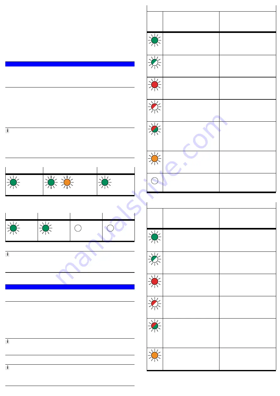
9.1
Behaviour of the Display Components after Error-free Commissioning
[MS] (green)
[NS] (green/orange)
[XF1], [XF2] (green)
Lights up
Lights up
1)
Lights up
1) The colour of the LED display is dependent on the network protocol used (green = EtherNet/IP,
orange = Modbus TCP)
Tab. 9 Display Components after Error-free Commissioning
[PS] (green)
[PL] (green)
[SF] (red)
[M] (yellow)
Lights up
Lights up
Off
Off
Tab. 10 Display Components after Error-free Commissioning
You can find information on troubleshooting in the event of incorrect behaviour in
the “Description of Automation system CPX-E” and the descriptions of the mod-
ules used
è
10
Service
NOTICE!
Accumulation of heat due to reduced air supply to electronics.
•
Keep the ventilation slots free and regularly remove contamination.
11
Diagnostics and fault clearance
11.1
Diagnostics options
Various options are available for diagnosing errors:
–
Internal system diagnostics
–
LED indicators on the product
11.2
Internal system diagnostics
The internal system diagnostics is described in the “Description of automation
system CPX-E”
è
11.3
LED Displays
The network-specific LED displays are described below.
The system-specific LED indicators are described in the documents for the auto-
mation system CPX-E
è
Module status [MS]
LED
(green,
red,
orange)
Meaning
Remedy
Lights up
green
Normal operating status
–
Flashes
green
Configuration of automation system CPX-E
not complete or not correct
Complete or correct configuration of the
automation system CPX-E.
Lights up
red
Error cannot be rectified
Contact Festo Service
è
Flashes
red
Error can be rectified
Check configuration of the
automation system CPX-E.
Flashes
altern-
ately
red/green
The automation system CPX-E is in self-
test mode.
–
Lights up
orange
Bootloader
–
Off
No logic power supply to the network
interface
Check logic power supply.
Tab. 11 Module Status [MS]
Network status [NS]
1)
LED
(green,
red,
orange)
Meaning
Remedy
Lights up
green
The automation system CPX-E is online
and has a network connection (normal
operating status).
–
Flashes
green
The automation system CPX-E is online
and has received an IP address but does
not have a configured network connection.
Check configuration of the
automation system CPX-E; it is possible
that the automation system CPX-E is not
assigned to a master/scanner.
Lights up
red
Communication has failed.
Non-permitted IP address set that is
already used in the network.
Correct IP address.
Flashes
red
One or more “I/O connections” are in the
“time-out state”.
Check the physical connection to the mas-
ter/scanner.
Flashes
altern-
ately
red/green
The automation system CPX-E is in self-
test mode.
–
Lights up
orange
Modbus TCP has control over the output
data.
Bootloader, if the LED [MS] is also lit up
orange
è
–


