background image

2.      Installation

2−6

Festo    P.BE−CPX−CEC−EN    en  1004a

2.3

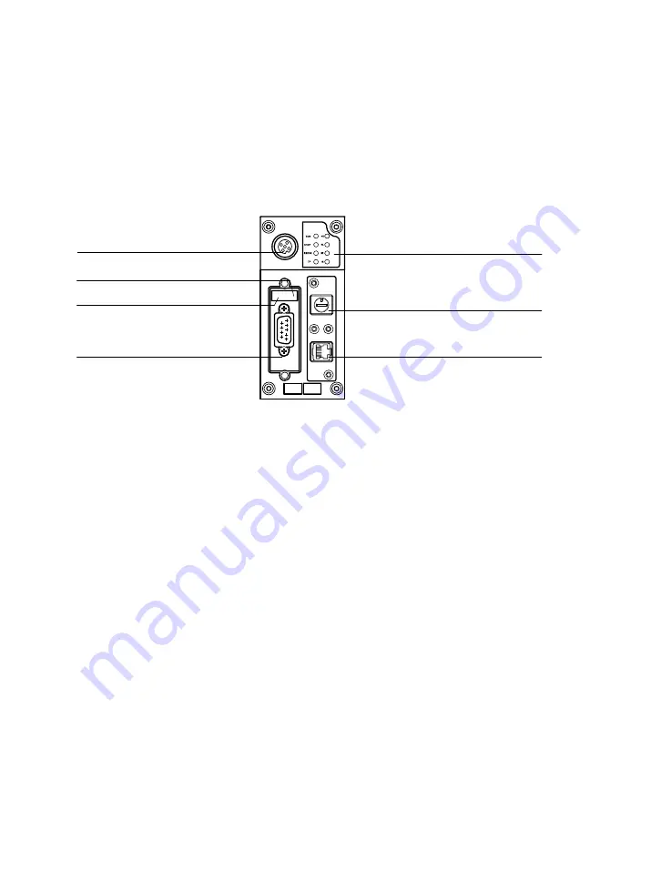
Connection  and  display  elements

2

3

4

6

7

5

1

1

Status  LEDs

2

RUN/STOP  rotary  switch

3

Ethernet  interface 
(10/100BaseT,  RJ45)

4

CPX−CEC−C1/−M1:
CANopen  interface


(plug,  9−pin,  Sub−D  )
CPX−CEC:
RS232  interface
(socket,  9−pin,  Sub−D)

5

DIL  switch  1

6

DIL  switch  2

7

Connection  for  a  handheld  of  type
CPX−MMI

Fig.2/2:

Connection  and  display  elements  (here  for  CPX−CEC−C1/−M1  as  an  example)

Содержание CPX-CEC

Страница 1: ...Electronics Manual CoDeSys Controller Type CPX CEC CPX CEC C1 M1 CPX Terminal Manual 569 122 en 1004a 753 482 ...

Страница 2: ......

Страница 3: ...any 2010 Internet http www festo com E mail service_international festo com The reproduction distribution and utilisation of this docu ment as well as the communication of its contents to others without explicit authorisation is prohibited Offenders will be held liable for the payment of damages All rights re served in the event of the grant of a patent utility module or design ...

Страница 4: ... respective trademark holders in certain countries Thisproduct usesopen sourcesoftwarewhichissubjecttothe GNUGeneralPublicLicense Version2 ThelicensingconditionsoftheGPLarelocatedeitherintheproduct sengineering tool or at the following addresses http IP address of the device product information html http www gnu org copyleft gpl html ...

Страница 5: ...ing environment 1 9 1 4 1 Programming languages 1 11 1 4 2 Libraries 1 12 1 4 3 Parameterisation 1 12 1 5 Meaning of the LED displays 1 13 1 5 1 CPX specific LEDs 1 14 2 Installation 2 1 2 1 General installation instructions 2 3 2 2 Dismantling and fitting 2 4 2 2 1 Dismantling 2 4 2 2 2 Fitting 2 5 2 3 Connection and display elements 2 6 2 4 Setting the switches of the CoDeSys controller 2 7 2 4 ...

Страница 6: ... steps 3 3 3 3 Configuration of the CPX modules 3 5 3 4 Configuration of the CANopen slaves 3 8 3 5 Parameterisation of the CPX terminal 3 9 3 5 1 Parameterisation via control configuration in CoDeSys 3 10 3 5 2 Parameterisation via the handheld type CPX MMI 3 13 3 6 Forcing 3 14 4 Diagnosis 4 1 4 1 General error response of the CoDeSys controller 4 3 4 2 Diagnosis via controller LEDs 4 5 4 3 Furt...

Страница 7: ...hernet The CPX terminal with the CPX CEC CPX CEC may only be used as follows as designated in industrial applications without any modifications by the user Only the conver sions or modifications described in the documentation supplied with the product are permitted in faultless technical condition only in combination with approved components e g valves drive displacement encoder combinations The l...

Страница 8: ...ol system programming errors in user programs and projects Simply switching off the compressed air supply or load voltage is not suitable for locking procedures In the event of a fault this could lead to unintentional movement of the drive Before doing mounting installation and service work bring the system into a safe condition e g by bringing the drive into a safe position and deactivating the c...

Страница 9: ...for example the standards listed under the EC Machinery Directive must be ob served Without additional measures in accordance with statutory minimum requirements the product is not suitable for use in safety related sections of control systems Protection from pressurised tubing Caution Danger of injury through inappropriate handling of pres surised tubing Undesired movements of the connected actua...

Страница 10: ...roup This manual is intended exclusively for technicians trained in control and automation technology who have experience in installing commissioning programming and diagnosing positioning systems Service Please consult your local Festo Service if you have any techni cal problems ...

Страница 11: ...on is made between the following danger warnings Warning means that failure to observe this instruction may result in serious personal injury or property damage Caution means that failure to observe this instruction may result in personal injury or property damage Note means that failure to observe this instruction may result in damage to property The following pictogram marks passages in the text...

Страница 12: ...the Festo product Environment Information on the environmentally friendly use of Festo products Text markings The bullet indicates activities which may be carried out in any order 1 Numerals denote activities which must be carried out in the numerical order specified Hyphens designate general lists Brackets designate menu entries Example Scan module configuration Arrow brackets mark placeholders f...

Страница 13: ...ntroller Further information on the device can be found in the followingdocumentation Type Title Description Short manual CoDeSys controller type P BE K CPX CEC Connection and display elements mounting installation and technical data Onlinehelp Online Help for the CoDeSys controller CPX CEC Configuration commissioning operationand error diagnosis Tab 0 1 Additional documentation on the device Gene...

Страница 14: ...nsisting of CPX modules with or without pneumatics CPX modules Common term for the various modules which can be integrated in a CPX terminal DHCP Dynamic Host Configuration Protocol Dynamic protocol for automatic assignment of IP addresses DIL switch Dual in line switches consist of several switch elements with which settings can be made I O modules Collective term for the CPX modules which provid...

Страница 15: ...f a bus slave on the CANopenfieldbus OLE Object Linking and Embedding OPC OLE for Process Control standardised software interface that permits access to process data PLC IPC Programmable logic controller industrial PC Pneumatic interface Interface between the modular electric peripherals and the pneumatics SoftMotion Motion functionality integrated in the CoDeSys pbF programming and run time syste...

Страница 16: ...otocol overhead compared to TCP This has the advantage of a faster exchange of data Due to the lack of a reply the correct transmission must be ensured e g by means of a user program User data Telegram data without protocol frame data The length of the user data is defined in the configuration of the fieldbus slave www World Wide Web Tab 0 2 Product specific terms and abbreviations ...

Страница 17: ...System summary 1 1 Festo P BE CPX CEC EN en 1004a Chapter 1 ...

Страница 18: ...EC CPX CEC 1 3 1 2 Supported motor controllers 1 5 1 3 The operating modes of the CoDeSys controllers 1 6 1 4 The CoDeSys provided by Festo programming environment 1 9 1 4 1 Programming languages 1 11 1 4 2 Libraries 1 12 1 4 3 Parameterisation 1 12 1 5 Meaning of the LED displays 1 13 1 5 1 CPX specific LEDs 1 14 ...

Страница 19: ... Process visualisation within CoDeSys provided by Festo with a type FED operator unit or with the software VipWin via Ethernet Additional process visualisation systems can be con nected via the supplied OPC server if they have an OPC client The CoDeSys controller controls a CPX terminal in the Stand Alone or Remote Controller operating mode Communication over fieldbus in connection with the use of...

Страница 20: ... software package SoftMotion for coordinated multi axis movements CPX CEC M1 can alternatively also be operated as a CANopen master The SoftMotion functions are then not available CPX CEC offers An RS232 interface Sub D 9 pin for connecting a type FED operator unit or for operating external devices With external devices data communication must be programmed by the user ...

Страница 21: ...otor controllers Motor controller Required firmware1 from Version CMMP AS 3 5 1501 2 1 CMMS AS 1 3 0 1 11 CMMS ST 1 3 0 1 7 the versions 1 3 0 1 10 and 1 3 0 1 12 are not supported SFC LAC 1 0 5 SFC LACI 1 0 CMMD 1 4 1 See rating plate for FCT plug in of the motor controller Tab 1 2 Supported motor controllers with CPX CEC M1 date June 2010 CPX CEC C1 M1 support up to 31 axes We recommend operatin...

Страница 22: ... in various operating modes depending on the demand Stand Alone Remote Controller Ethernet Remote Controller Fieldbus fieldbus node required The individual operating modes are briefly presented in the following Stand Alone operating mode 1 2 1 CPX CEC CPX CEC 2 CPX terminal controlled by the CPX CEC CPX CEC Fig 1 1 Stand Alone operating mode ...

Страница 23: ...CEC EN en 1004a Remote Controller Ethernet operating mode Ethernet 1 2 1 CPX CEC CPX CEC connected to an Ethernet network for communication 2 CPX terminal controlled by the CPX CEC CPX CEC Fig 1 2 Remote Controller Ethernet operating mode ...

Страница 24: ... Fieldbus operating mode 2 1 3 1 CPX CEC CPX CEC connected to the fieldbus for communication over the fieldbus node 2 CPX fieldbus node here CPX FB13 3 CPX terminal controlled by the CPX CEC CPX CEC Fig 1 3 Remote Controller Fieldbus operating mode fieldbus node required ...

Страница 25: ...itor Documentation with the integrated project documentation Debugging functions testing program sequence observing and changing variables error search CPX CEC M1 SoftMotion programming editors are integrated To be able to use a controller target under CoDeSys provided by Festo a so called Target Support Package is needed for the corresponding target This permits access to the system functions of ...

Страница 26: ...or the CoDeSys controller It also contains additional functions that are specially adapted to the CoDeSys controller Information about which functions of CoDeSys provided by Festo are supported by the CoDeSys controller and which additional functions are available can be found in the online help key word Functional Overview ...

Страница 27: ...WHILE DO as in high level languages Sequential function chart SFC Graphic programming languages Enables programming of sequences and so is suited for structuring and organising projects With transi tions and connections the sequential function chart describes the time sequence of the various steps within the program Function diagram FUN or Free graphic function diagram CFQ The function diagram wor...

Страница 28: ...ependently of projects such as modules declar ations and visualisations A library administrator with which you can integrate and view libraries is available for this purpose Detailed descriptions on the libraries and programming can be found in the online help 1 4 3 Parameterisation Information on parameterisation of the entire system via the CoDeSys controller can be found in the online help ...

Страница 29: ... the LEDdisplays The LEDs on the cover indicate the operating status of the device and are arranged in two groups 1 Controller LEDs see section 4 2 RUN STOP ERROR TP 2 CPX specific LEDs PS PL SF M 1 2 Fig 1 4 LED displays of the device here CPX CEC C1 M1 as an example ...

Страница 30: ... Operating voltage sensor supply outside the toler ance range Eliminate undervoltage LED flashes ON OFF Internal fuse for the operating voltage sensor supply has responded 1 Eliminate short circuit overload on module side 2 Depends on the parameterisation of the module module parameter The sensor supply voltage will be switched on again automati cally when the short circuit has been eliminated def...

Страница 31: ...F System Failure System error LED red Sequence 1 Meaning Error treatment LED is off ON OFF No error LED flashes ON OFF Simple error information error class 1 See description of error numbers in the CPX system manual LED flashes ON OFF Error error class 2 LED flashes ON OFF Serious error error class 3 1 The system error LED flashes depending on the class of error which has occurred Error class 1 mi...

Страница 32: ...w Sequence Meaning Error treatment LED is off ON OFF Force is not active LED flashes ON OFF Force is active The Force function is enabled see CPX system manual system parameter Force mode function no 4402 Tab 1 7 Displays of M LED Information on the controller LEDs can be found in section 4 2 ...

Страница 33: ...Installation 2 1 Festo P BE CPX CEC EN en 1004a Chapter 2 ...

Страница 34: ... 2 6 2 4 Setting the switches of the CoDeSys controller 2 7 2 4 1 RUN STOP rotary switch 2 7 2 4 2 DIL switches 2 8 2 5 Ethernet interface 2 10 2 5 1 Ethernet cable 2 10 2 6 Communication interfaces 2 12 2 6 1 CANopen interface CPX CEC C1 M1 2 12 2 6 2 RS232 interface CPX CEC 2 17 2 7 Connection of an operator unit type FED 2 18 2 8 Connection of a handheld type CPX MMI 2 19 2 9 Complying with pro...

Страница 35: ...e components Therefore do not touch any contacts Observe the handling specifications for electrostatically sensitive devices Note Check within the framework of your EMERGENCY STOP concept to ascertain the measures necessary for putting your machine system into a safe state in the event of an EMERGENCY STOP e g switching off power sources load voltage supply compressed air etc Information on fittin...

Страница 36: ...tling Dismantle the controller as follows 1 Loosen the four screws of the controller with a TORX screwdriver size T10 2 Pull the controller carefully and without tilting away from the contact rails of the interlinking block 1 CPX CEC CPX CEC 2 Interlinking block 3 Contact rails 4 Screws 3 4 1 2 Fig 2 1 Dismantling fitting of the controller here CPX CEC C1 M1 as an example ...

Страница 37: ...controller in the interlinking block Make sure that the grooves with the power contact terminals on the bottom of the controller lie above the contact rails 3 Push the controller carefully and without tilting as far as possible into the interlinking block 4 Place the screws so that the self cutting threads can be used Tighten the screws by hand 5 Tighten the screws with a TORX screwdriver size T10...

Страница 38: ...EDs 2 RUN STOP rotary switch 3 Ethernet interface 10 100BaseT RJ45 4 CPX CEC C1 M1 CANopen interface plug 9 pin Sub D CPX CEC RS232 interface socket 9 pin Sub D 5 DIL switch 1 6 DIL switch 2 7 Connection for a handheld of type CPX MMI Fig 2 2 Connection and display elements here for CPX CEC C1 M1 as an example ...

Страница 39: ...n 0 STOP during installation The switch setting of the RUN STOP rotary switch with four internal digital inputs is passed on to the controller and can be evaluated there Rotary switch Setting Meaning 0 STOP CoDeSys controller stopped The STOP LED lights up yellow 1 F RUN CoDeSys controller started The RUN LED lights up green Tab 2 1 Switch settings of the RUN STOP rotary switch ...

Страница 40: ...cessible in order to make settings Remove if applicable the cover or an IP65 IP67 plug from the Sub D interface DIL switch 1 DIL switch 1 is reserved Leave the two switch elements of DIL switch 1 at OFF CPX CEC CPX CEC DIL switch 1 Reserved DIL 1 1 OFF DIL 1 2 OFF Tab 2 2 Setting the DIL switch 1 ...

Страница 41: ... switch the CAN bus termination 120 on or off CPX CEC C1 M1 DIL switch 2 Termination switched off DIL 2 1 OFF DIL 2 2 OFF Termination switched on DIL 2 1 ON DIL 2 2 OFF All further switch settings are reserved The DIL switch 2 on the CPX CEC has no function Tab 2 3 Setting the DIL switch 2 ...

Страница 42: ...D n c n c Shield Transmitted data Transmitted data Received data not connected not connected Received data not connected not connected Screening Tab 2 4 Pin assignment of the Ethernet interface If the Ethernet interface is not used close it with the AK RJ45 cover In this way you will comply with protection class IP65 IP67 2 5 1 Ethernet cable Use as connecting cable Cable specification Screened fl...

Страница 43: ...tion In order to connect your CoDeSys controller to a network or PC you will require a patch or crossover cable The interface automatically recognises which cable is connected and automatically converts the signals Note Use the RJ 45 plug from Festo in order to comply with the protection class IP65 IP67 Type FBS RJ45 8 GS Observe the fitting instructions for the plug Fig 2 3 RJ 45 plug type FBS RJ...

Страница 44: ...ing plug n c CAN_L CAN_GND n c CAN_SHLD CAN_GND CAN_H n c n c FE not connected CAN low CAN ground not connected Connection to functional earth FE 2 CAN ground optional 1 CAN high not connected not connected The plug housing must be connected to FE 2 1 If a motor controller with external voltage supply is connected CAN ground optional pin 6 cannot be used on the CPX CEC C1 M1 2 FE Functional earthi...

Страница 45: ...esistor incorrect screened connection branches large distances unsuitable cables Use a twisted screened 4 core cable as a CAN bus line The CoDeSys controller communicates with the drive controllers via the CAN bus line If the Festo CAN bus plug is used a cable diameter of 5 8 or 7 10 mm is permitted Note If the CPX terminal is fitted onto the moving part of a machine the CAN bus line on the moving...

Страница 46: ...h max 0 4 Nm You can connect the CPX CEC C1 easily to the CAN bus with the CAN bus plug from Festo type FBS SUB 9 BU 2x5POL B You can disconnect the plug from the node without interrupting the bus line T Tap function Note The clamp strap in the Festo CAN bus plug is connected only capacitively internally with the metal housing of the sub D socket This prevents equalising currents from flowing via ...

Страница 47: ...ction window 2 Clamp strap for screened connection 1 3 Protective cap if connection is not used 4 CAN bus outgoing OUT 5 CAN bus incoming IN 6 SUB D plug 1 1 connected capacitively V GND H L SLD V GND H L SLD 2 1 3 4 5 6 Fig 2 4 CAN bus plug from Festo type FBS SUB 9 BU 2x5POL B ...

Страница 48: ...nnect the CAN bus interface Connect the screen There are further ways of connecting the CAN bus with adapters which can be ordered separately from Festo These adapters and additional accessories can be found under è www festo com catalogue M12 adapter 5 pin protection class IP65 type FBA 2 M12 5POL Screw terminal adapter 5 pin protection class IP20 type FBA 1 SL 5POL ...

Страница 49: ...ng external devices data communication must be programmed by the user Socket Pin Signal Explanation 1 2 3 4 5 6 7 8 9 Screen n c RxD TxD n c GND n c n c n c n c Screen not connected Received data Transmitted data not connected Data reference potential not connected not connected not connected not connected Connection to functional earth FE Tab 2 6 Pin assignment of the RS232 interface CPX CEC ...

Страница 50: ...tasks at the field level Follow the accompanying user documentation when installing the device Fig 2 5 CPX terminal with CPX CEC C1 and operator unit type FED incl optional Ethernet interface Connect an operator unit of type FED with Ethernet interface to the CoDeSys controller using an Ethernet cable With the CPX CEC connection can also take place over the RS232 interface ...

Страница 51: ...rogram download if parameters have been changed via the CoDeSys provided by Festo software This guarantees the consistency of the displayed data Use only the following original cables è www festo com catalogue for connecting the CPX MMI Type Cable length in m KV M12 M12 3 5 3 5 KV M12 M12 1 5 1 5 Tab 2 7 Connection cable for handheld type CPX MMI Further information on parameterisation via CPX MMI...

Страница 52: ...on IP65 IP67 Cover1 IP65 IP67 Ethernet RJ45 Plug type FBS RJ45 8 GS Cover2 type AK RJ45 Sub D CANopen RS232 and DIL switch Plug type FBS SUB 9 BU 2X5POL B Transparent cover2 type AK SUB 9 15 B Service interface M12 Connecting cable and plug of the CPX MMI Protective cap2 type ISK M12 Rotary switch Cover2 type AK RJ45 1 If connection is not used 2 Included in scope of delivery Tab 2 8 Connections a...

Страница 53: ...Commissioning 3 1 Festo P BE CPX CEC EN en 1004a Chapter 3 ...

Страница 54: ... commissioning 3 3 3 2 First steps 3 3 3 3 Configuration of the CPX modules 3 5 3 4 Configuration of CANopen slaves 3 8 3 5 Parameterisation of the CPX terminal 3 9 3 5 1 Parametrisation via control configuration in CoDeSys 3 10 3 5 2 Parametrisation via the handheld type CPX MMI 3 13 3 6 Forcing 3 14 ...

Страница 55: ... can be found on the accompanying CD ROM Observe the instructions on the cover of the CD ROM 2 Connect the PC to the CoDeSys controller 3 2 First steps The commissioning procedure described in the following sections uses the example of the CPX CEC C1 or CPX CEC M1 as a CANopen master Further information on commissioning the variants CPX CEC M1 with SoftMotion and CPX CEC can be found in the online...

Страница 56: ...elect the Root node if applicable 7 Open the Network configuration tab 8 Carry out the Search network function 9 Select the desired CoDeSys controller 10 Carry out the Set as active PLC function 11 Save the project You can now log in to the controller if necessary Fig 3 1 Network configuration using the example of the CPX CEC C1 ...

Страница 57: ...eated a new project in section 3 2 and selected the desired CoDeSys controller now continue commissioning with configuration of the CPX modules 1 Click in the window PLC Configuration on the nodes to the left of the CPX CEC 2 Click with the right mouse button on the element IOModules FIX Fig 3 2 Configuration of the CPX modules Now you can perform module configuration automatically or manually ...

Страница 58: ...configuration function if you want to perform module configuration automatically The I O modules of a CPI module are not included in auto matic module configuration In this case carry out a manual module configuration see next section or perform the Scan function in the CP Modules tab Fig 3 3 CP Modules tab ...

Страница 59: ... at position 0 From the list of the CPX modules select the CPX module to the right of CPX CEC Repeat Append Subelement until you have selected all CPX modules Addressing of inputs and outputs takes place automatically preset in the delivery condition of the device For each mod ule at least 4 bytes of inputs or outputs are reserved The rotary switch of the CPX CEC C1 for example occupies only 4 bit...

Страница 60: ...s results in a change of the address assignment of the CANopen slaves 1 In the PLC Configuration window click with the right mouse button on the Root node of the CoDeSys con troller 2 In the Append Subelement menu option choose the option CANopen master The CANopen master appears in the Control configuration after the IOModules 3 Click on CANopenMaster VAR with the right mouse button 4 Choose Appe...

Страница 61: ...fications on the parameters and data as well as basic information on parameterisation of the CPX terminal can be found in the CPX system manual type P BE CPX SYS Detailed information on the module parameters can be found in the user documentation of the respective modules The following parameterisation options are available Parameterisation via Description Properties Controlconfiguration in CoDeSy...

Страница 62: ...an be undertaken for the setpoint configuration logout parameters are transferred when the project is loaded When the relevant dialogue has been opened you can view and modify the individual parameters Parameters cannot be changed in the online mode In the following parameterisation is described using the example of the Root node Click in PLC Configuration on the symbol for the CPX CEC Settings Se...

Страница 63: ...odule 0 tab you receive the following information on the CoDeSys controller Fig 3 5 Module 0 tab Network configuration logout Look for the controller for which you want to prepare the new CoDeSys project in the Network configuration tab Fig 3 6 Network configuration tab ...

Страница 64: ... BE CPX CEC EN en 1004a System parameters Set the system parameters in the System Parameters tab Fig 3 7 System Parameters tab Trace parameters Set the following parameters in the Trace Parameters tab Fig 3 8 Trace Parameters tab ...

Страница 65: ...re saved only locally in the CPX terminal and are lost with Power OFF ON The connection with the CPX MMI is interrupted during a program download if parameters have been changed via the CoDeSys provided by Festo software Parameters changed by the CPX MMI and Festo_CPX lib are only then overwritten during the project download if parameter changes have also been made in the CoDeSys project Further i...

Страница 66: ...ith handheld type CPX MMI Forcing an input does not modify the input signal itself and cannot be observed at the relevant status LED The logical status of the input changes internally and in some cases has an effect on the program The forced input status is trans ferred to the image table of the inputs The online display in CoDeSys provided by Festo therefore shows the forced input signal Forcing ...

Страница 67: ... image table and are therefore not recognised by the controller They are not therefore represented in the online display You have various ways of temporarily influencing input or output signals e g for test purposes Forcing via the handheld type CPX MMI Forcing with the online display in CoDeSys provided by Festo Further information on forcing can be found in the CPX system manual type P BE CPX SY...

Страница 68: ...3 Commissioning 3 16 Festo P BE CPX CEC EN en 1004a ...

Страница 69: ...Diagnosis 4 1 Festo P BE CPX CEC EN en 1004a Chapter 4 ...

Страница 70: ...4 Diagnosis 4 2 Festo P BE CPX CEC EN en 1004a Contents 4 Diagnosis 4 1 4 1 General error response of the CoDeSys controller 4 3 4 2 Diagnosis via controller LEDs 4 5 4 3 Further diagnostic options 4 7 ...

Страница 71: ...es Include error handling mechanisms for all error categories in the user program Make sure that no persons are in the operating range of the drives or any other connected actuators The CoDeSys controller makes available the following error handling mechanisms in user programs System event CPX_system_fault Channel module diagnosis in the flag words Module support in the Festo_CPX lib Detailed info...

Страница 72: ...ee section 4 2 CPX specific LEDs see section 1 5 Handheld type CPX MMI Fast on the spot recognition of faults See CPX system manual Control configuration Online diagnosis without programming See online help User program Detailed diagnostic evaluation System event CPX_system_fault Channel module diag nosis in the flag words Module support in the Festo_CPX lib See online help Tab 4 1 Diagnostic opti...

Страница 73: ...TOP switch is in position 1 F LED is off ON OFF PLC program stopped RUN STOP switch is in position 0 Set RUN STOP switch to position 1 F Tab 4 2 Displays of RUN LED STOP PLC status stopped LED yellow Sequence Status Error number Error handling LED lights up ON OFF PLC program stopped RUN STOP switch is in position 0 LED is off ON OFF PLC program started RUN STOP switch is in position 1 F Set RUN S...

Страница 74: ...d or CoDeSys pbF LED is off ON OFF No error Tab 4 4 Displays of ERROR LED TP Ethernet connection link traffic LED green Sequence Status Error number Error handling LED lights up ON OFF Ethernet connection OK LED flashes ON OFF Data transfer active LED flashes irregularly LED is off ON OFF Ethernet connection to the parameterisation PC not OK Check the connection the IP address Tab 4 5 Displays of ...

Страница 75: ... diagnostics options Further information on diagnosis via the control configuration in CoDeSys provided by Festo and via user programs can be found in the online help Further information on diagnostics with SoftMotion CPX CEC M1 can be found in the online help ...

Страница 76: ...4 Diagnosis 4 8 Festo P BE CPX CEC EN en 1004a ...

Страница 77: ...Technical appendix A 1 Festo P BE CPX CEC EN en 1004a Appendix A ...

Страница 78: ...A Technical appendix A 2 Festo P BE CPX CEC EN en 1004a Contents A Technical appendix A 1 A 2 Technical data A 3 ...

Страница 79: ...per IEC 61131 3 LDR STL ST FUN SFC also CFC Program memory 4 MB user program Protocol CoDeSys Level 2 EasyIP Modbus TCP TCP IP Device specific diagnostics Channel and module oriented diagnostics Undervoltage short circuit of modules Diagnostic memory Additionalfunctions CPX CEC CPX CEC CPX CEC C1 CPX CEC M1 CPX CEC Diagnosticfunctions Motion functions for electric drives SoftMotion functions for e...

Страница 80: ...5 250 500 1 000 kbps adjust via software Yes Data interface CPX CEC Type Connectiontechnology Transmissionspeed Electrical isolation RS232 interface Socket Sub D 9 pin 9 6 230 4 kbps Yes Ethernet Number Connector plug Transmissionspeed Supported protocols 1 RJ45 socket 8 pin 10 100 mbps TCP IP EasyIP Modbus TCP Protection class only in conjunction with plugs and covers in protection class IP65 IP6...

Страница 81: ...o P BE CPX CEC EN en 1004a CPX CEC CPX CEC Power failure bridging 10 ms Storage temperature 20 70 C Ambient temperature 5 50 C Relative air humidity 95 non condensing Product weight 155 g Dimensions W x L x H 50 mm x 107 mm x 55 mm ...

Страница 82: ...A Technical appendix A 6 Festo P BE CPX CEC EN en 1004a ...

Страница 83: ...Index B 1 Festo P BE CPX CEC EN en 1004a Appendix B ...

Страница 84: ...B Index B 2 Festo P BE CPX CEC EN en 1004a ...

Страница 85: ...CAN bus Connecting 2 13 Connection 2 16 Line 2 13 Termination 2 9 CoDeSys provided by Festo XII 1 9 Commissioning 3 3 Configuration CANopen slaves 3 8 CPX modules 3 5 Connection and display elements 2 6 CPX MMI 2 19 D Designated use V Diagnosis 4 4 Dismantling 2 4 F Firmware XI Fitting 2 4 Forcing 3 14 Front end display FED 2 18 ...

Страница 86: ... 17 L LEDs Controller LEDs 4 5 CPX specific 1 13 M Motor controllers supported 1 5 O Operating modes 1 6 Operator unit type FED 2 18 P Parameterisation Via control configuration 3 10 Via handheld type CPX MMI 3 13 Parameterisation of the CPX terminal 3 9 Pin assignment CANopen interface 2 12 Ethernet interface 2 10 RS232 interface 2 17 ...

Страница 87: ...n class IP65 IP67 2 20 S Service VIII SoftMotion 1 3 Commissioning 3 3 Diagnosis 4 7 Meaning XIII Strain relief 2 13 Switch DIL switch 2 8 2 9 RUN STOP rotary switch 2 7 System parameters 3 12 T Target group VIII Technical data A 3 U User instructions IX ...

Отзывы: