


Requirements for the connecting cable
Structure
Only use cables that ensure reinforced isolation
between the motor phases and the shielded sig-
nals of the holding brake and motor temperature
sensor in accordance with IEC 61800-5-1.
7.9.4 Shield support of the motor cable
Max. cable length
7.6 Information on EMC-compliant installa-
Max. capacitance
<
250 pF/m
Nominal cross section of power wires
1)
CMMT-AS-C7-11A-P3
2)
0.75 mm
2
…
1.5 mm
2
CMMT-AS-C12-11A-P3
3)
1.5 mm
2
…
2.5 mm
2
Cable diameter of the stripped cable or shield sleeve (clamping range of the shield clamp)
CMMT-AS-C7/C12-11A-P3
12 mm
…
17 mm
The only motor cables permitted are those that fulfil the requirements of EN 61800-5-2, Annex D.3.1
and the requirements of EN 60204-1.
1) Shield clamp and mating connector also permit larger cross sections.
2) for 0.75 mm² check that the shield diameter is sufficient for proper clamping
3) 2.5 mm² is recommended for cable lengths over 50 m to limit the voltage loss of the available output
voltage.
Tab. 31: Requirements for the connecting cable
Festo offers prefabricated motor cables as accessories
–
Only use motor cables that have been approved for operation with the Festo
servo drive. Motor cables of other manufacturers are permitted if they meet the
specified requirements.
7.9.2
[X6B], motor auxiliary connection
The connection [X6B] is located on the front of the device. The holding brake
of the motor and the motor temperature sensor can be connected to the connec-
tion [X6B]. The output for the holding brake is used both functionally and in
connection with the safety sub-function Safe brake control
è
Manual Safety
sub-function.
To allow motor temperature monitoring, the following are supported:
–
N/C and N/O contacts
–
KTY 81 … 84 (silicon temperature sensors)
–
PTC (PTC resistor, positive temperature coefficient)
–
NTC (NTC resistor, negative temperature coefficient)
–
Pt1000 (platinum measuring resistor)
The servo drive monitors whether the motor temperature violates an upper or
lower limit. With switching sensors, only the upper limit value can be monitored
(e.g. with a normally closed contact). The limit values and the error response can
be parameterised.
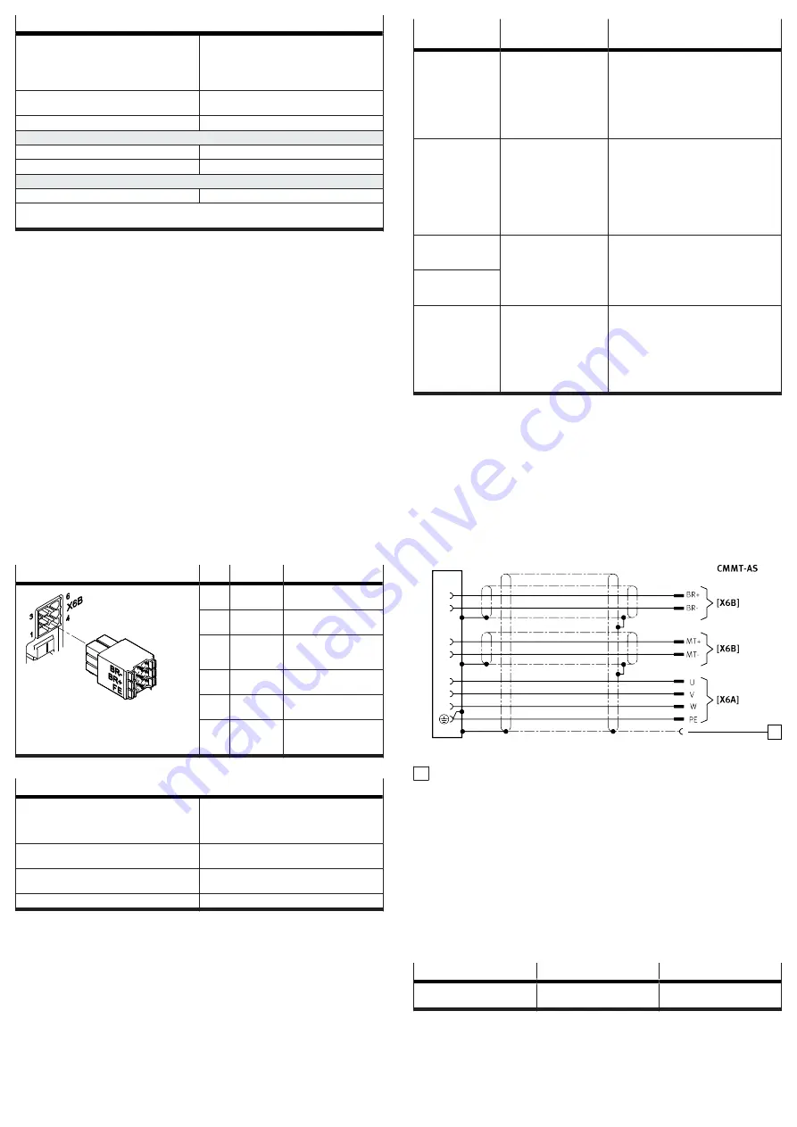
[X6B]
Pin
Function
Description
6
MT–
Motor temperature (neg-
ative potential)
5
MT+
Motor temperature (posi-
tive potential)
4
FE
Functional earth con-
nected to protective
earth
3
BR–
Holding brake (negative
potential)
2
BR+
Holding brake (positive
potential)
1
FE
Functional earth con-
nected to protective
earth
Tab. 32: Motor auxiliary connection
Requirements for the connecting cable
Structure
–
2 wires for the line to the holding brake,
twisted in pairs, separately shielded
–
2 wires for the line to the temperature sensor,
twisted in pairs, separately shielded
Min. conductor cross section including wire end
sleeve with plastic sleeve
0.25 mm
2
Max. conductor cross section including wire end
sleeve with plastic sleeve
0.75 mm
2
Max. length
100 m
1)
1) Take voltage drop into account for cable lengths
>
25 m by selecting suitable cross-sections for the
insulated wires.
Tab. 33: Requirements for the connecting cable
Requirement for the temperature sensor in the motor
–
electrically reinforced isolation from the motor phases in accordance with
IEC 61800-5-1, voltage class C, overvoltage category III.
Shield support requirements
–
Connect the cable shield on both sides.
–
Make unshielded cable ends as short as possible (recommended 150 mm,
max. 200 mm).
7.9.3
Electronic overload and over temperature protection for the motor
The CMMT-AS allows the motor to be electronically protected against overload
and provides over temperature protection with the following protective functions:
Protective func-
tions
Description
Measures required during installa-
tion and commissioning
Temperature moni-
toring of the motor
The motor temperature is
monitored for an upper and
lower limit value, including
hysteresis. The limit values
can be parameterised.
–
Connect the temperature sensor to connec-
tion [X6B] (both switching and analogue
temperature sensors are supported)
–
Parameterise the temperature limit values
in accordance with the type of motor
used, e.g. using the device-specific plug-
in. Comply with the permissible limit
values of the motor.
Electronic current
limiting and I²t mon-
itoring of the motor
current
The motor current is
monitored electronically
and limited in accordance
with the limit values
specified in the standard
è
EN 61800-5-1, Tab. 29.
Motor currents and I²t time
constant can be parameter-
ised.
–
Parameterise the nominal current, max-
imum current and I²t time constant of the
motor, e.g. using the device-specific plug-
in.
Thermal memory in
the event of motor
switch-off
supported, cannot be para-
meterised
–
none
Thermal memory in
the event of a power
supply failure
Speed-sensitive over-
load protection
supported from firmware
version V019, parameteris-
able
–
Parameterise I²t monitoring with speed-
dependent scaling, e.g. with the device-
specific plug-in.
Such as for:
–
Synchronous servo motors (lower permis-
sible current at high rotational speed)
–
Fan motors (lower permissible current at
low rotational speed)
Tab. 34: Protective functions for the motor
The specified parameters are preset for Festo motors. The parameters can be
adapted in the plug-in.
7.9.4
Shield support of the motor cable
Requirements for the motor cable shield support on the device side
The type of shield support depends on the design of the motor cable. If,
for example, a hybrid cable is used to connect the motor, holding brake and
temperature sensor, the following options are available for connecting the shield
on the device side:
Option 1: all motor cable shields are jointly connected over a wide surface area
using a shield sleeve at the cable end and are connected below the shield clamp
on the front of the CMMT-AS.
1
Fig. 9: Shared shield support of all cable shields (example)
1 Shield sleeve
Option 2: the outside shield of the motor cable is connected separately over a
wide surface area below the shield clamp on the front of the CMMT-AS. The inside
shields are connected separately to the designated FE pin of the connection [X6B].
•
Make unshielded cable ends as short as possible.
Mounting the shield clamp
The lower section on the front of the housing is used as a shield support surface.
The shield support surface, together with the shield clamp, allows the motor cable
shield to be connected over a wide surface area
1. Using the shield clamp, press the motor cable shield or the conductive shield
end sleeve of the motor cable onto the shield support surface of the housing.
2. Tighten the retaining screws (2x) of the shield clamp with a size T20 TORX
screwdriver. Pay attention to the clamping range and observe the tightening
torque specified below.
Property
Value
Comments
Clamping range
12 mm … 17 mm
Diameter of the stripped cable
or shield sleeve