


Property
Value
Comments
Tightening torque for the
retaining screws in the case of
block mounting
1.8 Nm ± 15%
In the case of block mounting,
the shield clamp makes full
contact with the base of
the housing (cable diameter
12 mm)
Minimum tightening torque
with larger cable diameter
(
>
12 mm … 23 mm)
0.5 Nm ± 15%
With a higher tightening
torque, make sure that the
connecting cable does not get
crushed in the clamping area
due to excessive pressure.
Tab. 35: Tightening torque and clamping range CMMT-AS-...-C7/C12-11A-P3
1
2
3
4
5
Fig. 10: Shield clamp of the motor cable
1
Retaining screws of the shield
clamp (2x)
2
Motor cable
3
Cut-out for mounting cable
binders (2x)
4
Shield clamp
5
Shield of the motor cable posi-
tioned under the shield clamp
over a wide area
Motor cable shield support on the motor side
Detailed information on the motor-side connection with motor cables from Festo
è
Assembly instructions for the motor cable
•
Connect all shields to the PE over a wide surface area on the motor side,
e.g. via the shield connection provided on the motor connector or the shield
support surface in the motor junction box.
7.10
Power and logic voltage supply
7.10.1
[X9A], power supply and DC link circuit connection
The connections for the power voltage supply and the DC link circuit are not
protected against wiring errors. The reversal of the connections results in a device
defect during switch-on.
With cross-wiring, observe the polarity of the DC link connection on all devices.
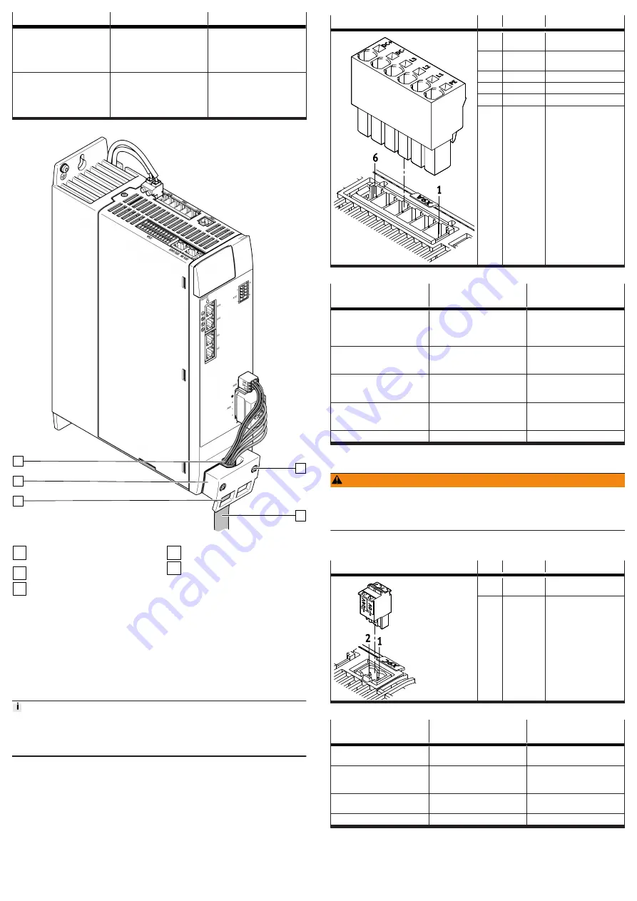
[X9A]
Pin
Function
Description
6
DC+
DC link circuit positive
potential
5
DC-
DC link circuit negative
potential
4
L3
Mains supply phase L3
3
L2
Mains supply phase L2
2
L1
Mains supply phase L1
1
PE
Protective earthing
Tab. 36: Power supply and DC link circuit
Requirements for the
connecting cable
Single device
Device compound
Number of insulated wires and
shielding
4 insulated wires, unshielded
Without DC link coupling:
4 wires, unshielded
With DC link coupling: 6 wires,
unshielded
Min. conductor cross section
including wire end sleeve with
plastic sleeve
0.5 mm
2
1.5 mm
2
Max. conductor cross section
including wire end sleeve with
plastic sleeve
4 mm
2
4 mm
2
Max. conductor cross section
including wire end sleeve
without plastic sleeve
6 mm
2
6 mm
2
Max. length
2 m
£
0.5 m
Tab. 37: Requirements for the connecting cable
7.10.2
[X9C], logic voltage supply
WARNING
Risk of injury due to electric shock.
• For the electrical power supply with extra-low voltages, use only PELV circuits
that guarantee a reinforced isolation from the mains network.
• Observe IEC 60204-1/EN 60204-1.
•
Only connect PELV circuits with an output current of max. 25 A. Otherwise,
use a separate external fuse: 25 A.
[X9C]
Pin
Function
Description
2
24 V DC
Positive potential of logic
voltage supply
1
0 V
Reference potential for
logic voltage supply
Tab. 38: Logic voltage supply
Requirements for the
connecting cable
Single device
Device compound
Number of insulated wires and
shielding
2 insulated wires, unshielded
2 insulated wires, unshielded
Min. conductor cross section
incl. wire end sleeve with
plastic sleeve
0.5 mm
2
0.5 mm
2
Max. conductor cross section
incl. plastic wire end sleeve
2.5 mm
2
2.5 mm
2
Max. length
2 m
0.5 m
Tab. 39: Requirements for the connecting cable
7.10.3
[X9B], connection for braking resistor
The connection [X9B] is located on the top of the device. The internal braking
resistor or a suitable external braking resistor is attached to the connection [X9B].