


5. Functional safety engineering
52
Festo P.BE-CMMP-AS-3A-HW-EN 0708NH
t
1
t
2
t
3
t
5
t
6
t
7
t
8
t1
0
t1
1
t1
2
t1
3
t
9
t
4
t
t
t
t
t
t
t
t
t
Triggering of pulse amplifier supply relay (optocoupler driver)
X3.2 (24V)
X3.2 (0V)
Supply of pulse amplifiers (optocoupler driver)
“ON“ (15V)
“OFF”
Floating feedback contact for driver supply
(X3.5/6)
open
closed
Output stage enabling (X1, DIN4)
“ON”
Timing of output
stage enabling
variable
Controller enabling (X1, DIN5)
Holding brake control (X6.1/2)
Released
(24V)
Fixed
(0V)
Internal output stage enabling
(controlled by µP)
Set speed "n"
n=0
n
“H”
“H
”
“H”
Seven-segment
display
Delay until brake is
released!
Delay until brake is
applied!
Timing of "safe stop"
activation variable.
To be determined by user,
e.g. by means of safety
switching devices, depending
on application.
2. shut-down path
1. shut-down path
Discharge curve of
electrolytic capacitors for the
supply of the pulse amplifiers
"safe stop"
"safe stop"
“OFF”
“ON”
“OFF”
Can be set via FCT
Both ramps ca be set
separately via FCT
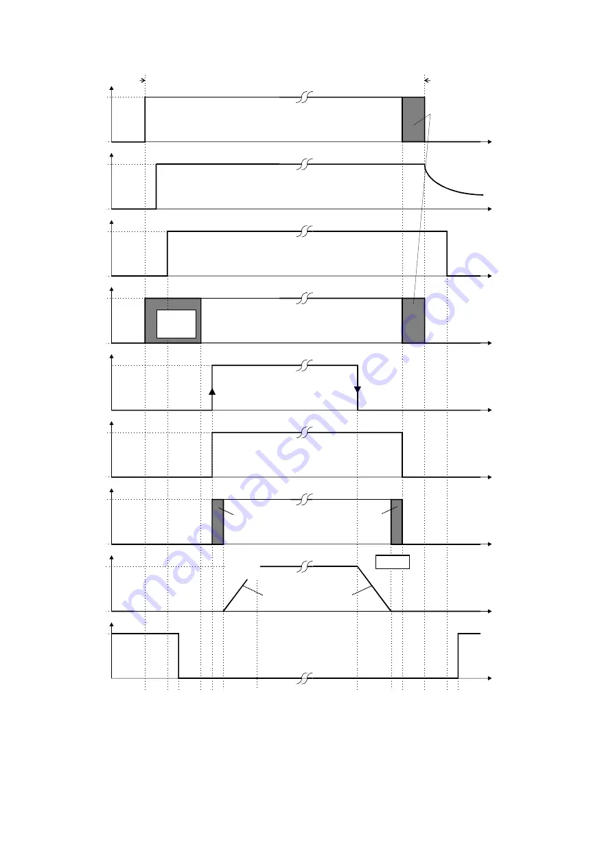
Fig. 5.2 "Safe standstill" timing as per EN 954-1 Category 3
Description of the timing diagram:
This timing diagram is based on the example of speed regulation using the controller en-
able DIN 5 at [X1]. For Fieldbus applications, the controller enable is additionally controlled
FCT
Содержание CMMP-AS-C2-3A
Страница 2: ......