


A. Technical specifications
104
Festo P.BE-CMMP-AS-3A-HW-EN 0708NH
A.3
Motor connection [X6]
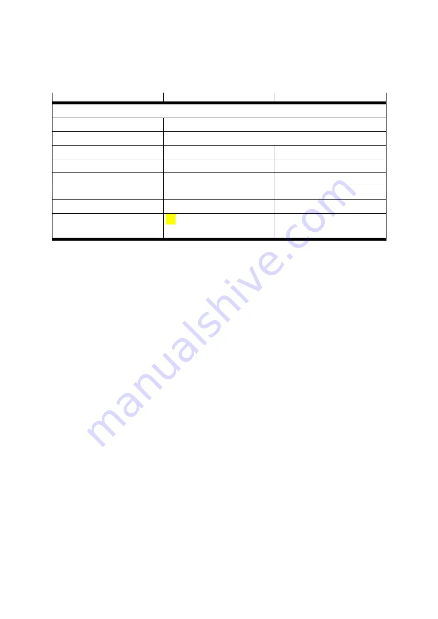
Type CMMP-AS-C2-3A
Type CMMP-AS-C5-3A
Data for operation with 1x 230 VAC [± 10%], 50 Hz
Output voltage
0 … 270 VAC
Output frequency
0 … 1,000 Hz
Output power
0.5 kVA
1.0 kVA
Max. output power for 5 s
1.0 kVA
2.0 kVA
Output current
2.5 A
eff
5 A
eff
Max. output current for 5 x
5 A
eff
10 A
eff
Clock frequency
max. 12.5 kHz
max. 12.5 kHz
Max. mains current in continuous
operation
2.4 A
eff
4.7 A
eff
Table A.12 Technical data: Motor connection data [X6]
For connecting the internal braking resistor, please observe table 7.1 page 68.
A.4
Angle encoder connections [X2A] and [X2B]
Various feedback systems can be connected to the CMMP-AS servo positioning controller
via the universal encoder interface:
-
Resolver (interface [X2A])
-
Encoder (interface [X2B])
-
Incremental encoder with analogue and digital tracking signals
-
SinCos encoder (single/multi-turn) with HIPERFACE
-
Multi-turn absolute value encoder with EnDat
The shaft encoder type is then defined using the parameterising software.
The feedback signal is available for subsequent drives via the incremental encoder output
[X11].
It is possible to analyze two encoder systems in parallel. When doing this, the resolver for
the current regulation is usually connected to [X2A], e.g. an absolute value encoder as a
feedback signal for the position controller is connected to [X2B].
A.4.1
Resolver connection [X2A]
Commonly available resolvers are connected to the 9-pin D-SUB connection [X2A]. Single
and multi-pole resolvers are supported. The number of pole pairs in the resolver must be
specified by the user in the parameterising software so that the CMMP-AS can correctly
determine the speed. The pole pair number of the motor (P
0Motor
) is always a whole multiple
of the pole pair number of the resolver (P
0Resolver
). Incorrect combinations generate an error
message during motor identification, e.g. P
0Resolver
= 2 and P
0Motor
= 5.
Содержание CMMP-AS-C2-3A
Страница 2: ......