USE AND
MAINTENANCE MANUAL
Pressa manuale idraulica e pneumatica
Art. P001/75
TRANSLATION OF THE ORIGINAL INSTRUCTIONS
fervi.com
Страница 1: ...USE AND MAINTENANCE MANUAL Pressa manuale idraulica e pneumatica Art P001 75 TRANSLATION OF THE ORIGINAL INSTRUCTIONS fervi com ...
Страница 2: ...ne must have all the necessary information and instruction and should be given adequate training in relation to safety regarding a Conditions of use for the equipment b Foreseeable abnormal situations pursuant to Article 73 of Legislative Decree 81 08 We guarantee the Machine complies with the specifications and technical instructions described in the Manual on the date of issuance and listed here...
Страница 3: ...INE SAFETY DEVICES 13 6 IMPROPER USES AND PRECAUTIONS 14 7 TRANSPORTING LIFTING AND DISPLACEMENT 15 8 ASSEMBLY AND COMMISSIONING 16 8 1 General warnings 16 8 2 Unpacking instructions 16 8 3 Press assembly 17 8 4 Press installation 19 8 5 Preliminary testing 19 9 MACHINE OPERATION 20 9 1 Adjusting table height 20 9 2 Manual pressing work 21 9 3 Removing air from the circuit 22 9 4 Pressing work wit...
Страница 4: ...MACHINES AND ACCESSORIES Page 4 of 29 fervi com ...
Страница 5: ...ary condition for safe and satisfactory operation of the machine Before starting operation installation and use of the Pressa manuale idraulica e pneumatica authorized staff must therefore read this technical document carefully know which protections and safety devices are available on the machines their location and how they work The buyer is responsible for ensuring that users are properly train...
Страница 6: ... be read carefully in order to acquire the necessary knowledge In other words durability and performance are strictly dependent on how it is used Even if already familiar with the Pressa manuale idraulica e pneumatica it is necessary to follow the instructions contained herein in addition to the general precautions to be observed while working Acquire full knowledge of the machine Read this manual...
Страница 7: ...er to avoid damage to persons to the property or to the machine itself Please only use the machine for its envisaged uses Don t tamper with the safety devices equipping the machine Risks associated with using the machine Before starting any work on the machine the operator must wear the appropriate personal protective equipment PPE such as gloves and eye protection 1 Always check the efficiency an...
Страница 8: ...l in its entirety 15 The company safety manager is responsible for monitoring the company s risk status according to Legislative Decree no 81 08 2 2 Safety regulations for hydraulic presses Compression and impact The operation of lifting loads ALWAYS entails a risk related to the possibility of the load falling even if handled properly There is NO intrinsic means of safety just as there is NOworke...
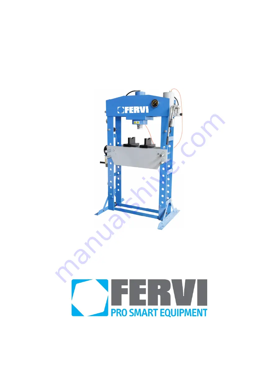
Страница 9: ... any damage resulting therefrom Compression and impact The press was designed and manufactured for a specific use different uses and non compliance with the technical parameters established by the Manufacturer may constitute dangerous conditions for the operator This with particular reference to the size shape and materials of the pressed pieces The hydraulic pneumatic press consists of Steel fram...
Страница 10: ...the Machine 1 Pressure gauge 7 Compressed air line 2 Hydraulic piston plunger 8 Pallet carrier displacement winch 3 Supporting beam column 9 Support pins with cotter pin 4 Table 10 Support posts 5 Hydraulic pump 11 Support feet 6 Pump levers 12 Lower beam 1 2 3 4 5 6 7 8 9 10 11 12 fervi com ...
Страница 11: ...there is the identification plate illustrated below Figure 2 Identification plate MAXIMUM CAPACITY VALUE The labels specify the maximum capacity under standard conditions This value indicates the maximum pressing force the machine can exert P001 75 Maximum pressing force capacity 750 kN 75 000 kg approx fervi com ...
Страница 12: ...MACHINES AND ACCESSORIES Page 12 of 29 4 3 Warning pictograms There are several warning pictograms attached to the machine Figure 3 Warning pictograms fervi com ...
Страница 13: ...osition when the pressure in the hydraulic circuit is discharged being a single acting hydraulic cylinder The press is also equipped with pallet carrier and pressing plate locking pins supplied with cotter pins After adjusting the height of the pallet carrier the steel pins hold it in a stable secure position There are two pins for each side of the pallet carrier Figure 4 Locking pins Use of PPE I...
Страница 14: ...ly secured to the floor To use the press on yielding surfaces and in any case with insufficient strength to support the load To leave the manual press unattended when it is loaded with the circuit under pressure To exceed the pressing force capacity and or the maximum pressure indicated on the label To move the table while the press is loaded with the circuit under pressure To allow untrained pers...
Страница 15: ...n Lifting the presses requires equipment with a capacity of at least 600 kg Do not use makeshift equipment and do not attempt to lift manually Do not move the press when there are people within the operating range of lifting equipment If the press has to be moved after assembly it is necessary 1 To remove the mounting bolts from the floor 2 Use a forklift truck inserting the forks as described in ...
Страница 16: ...en the difficulty and importance of machine assembly and commissioning poor execution thereof may lead to serious safety risks for exposed persons both at this stage and during subsequent operation Figure 7 Packaging conditions 8 2 Unpacking instructions The press is supplied in a wooden box Before disposing of the packaging ensure all machine parts eg screws the owner s manual and other documenta...
Страница 17: ...washer Ref 05 in the figure and a nut Ref 04 in the figure Figure 8 Side supports installation 3 Assemble the pressure gauge Ref 43 in the figure by screwing it clockwise into the appropriate housing Ref 32 in the figure Tighten the nut as securely as possible Ref 44 in the figure to prevent leakage from the circuit Figure 9 Pressure gauge installation 4 Assembling the pump unit connect the pump u...
Страница 18: ...ll the two levers in their appropriate housing screwing in the locking bolts Figure 11 Installing the connecting pipes Air outlet valve Before proceeding with the assembly open the air vent valve inside the cylinder Ref 61 5 Move the manual winch Ref 11 in the figure into position next to the machine and connect it to the bracket Ref 34 in the figure using the screws Ref 02 in the figure washers R...
Страница 19: ...e position using the fastening holes on the brackets themselves Use appropriate fastening devices such as bolts dowels etc 2 Securely tighten the mounting bolts grips 8 5 Preliminary testing Before using the press it is necessary and essential to carry out a preliminary test in its place of operation The test includes a general visual inspection of the machine to ensure there are no worn parts and...
Страница 20: ...y Place the table and pressing plate at the required height depending on the size of the workpiece as follows 1 Unload the table removing all wedges and pressing plates 2 Use the manual winch to slightly lift the pallet and therefore remove weight from the four support pins Crushing Do not attempt to operate the winch with your hands near the teeth of the winch itself Always use the handle 3 Remov...
Страница 21: ...sure against falling Re insert the locking cotter pins on all the pins 6 Loosen the strain of the cable by operating the winch handle completely resting the pallet carrier on the pins as soon as they are assembled 9 2 Manual pressing work 1 Place the workpiece to be pressed on the press plate centred with respect to the piston The pieces to be pressed should have a compact and solid structure and ...
Страница 22: ...ents 4 Put the press hydraulic circuit under pressure controlling the reading of the pressure gauge until it reaches the desired strength Figure 16 Pressure gauge Pressure gauge The gauge has two measuring scales an internal scale in METRIC TONS or Tons in the International System of Measurement an external scale in U S TONS or Tons in the Anglo Saxon System of Measurement 9 3 Removing air from th...
Страница 23: ...lever of the valve to activate the pump and put the hydraulic oil under pressure Figure 17 Pneumatic pump and control valve 9 5 Pressure release Use the release valve on the pump to release the pressure of the hydraulic circuit and actuate the upstroke of the plunger Specifically unscrew the valve knob in an anticlockwise direction Figure 18 Release valve At the end of the upward stroke re tighten...
Страница 24: ...ition hydraulic circuit not under pressure before performing any maintenance operation 10 1Routine maintenance INTERVENTION Frequency Daily Weekly Monthly 1 General visual inspection X 2 Check that plates are clearly visible and legible X 3 Check for leaks in the hydraulic circuit X 4 Check the oil level X 5 General cleaning X 6 Check the wear of the pressing piston X 7 Check the tightness of the ...
Страница 25: ...or engine oil 5 General cleaning cleaning is necessary to free the structure and moving parts from the accumulation of dust dirt and stains caused by excess lubricants Cleaning should be done with the use of means equipment and detergents or solvents commonly used in the cleaning of industrial equipment 6 Check the wear of the pressing piston check that the piston pressing surface is not worn out ...
Страница 26: ...e A The release valve is not properly closed B There is air in the system A Check and close the release valve B Release air from the circuit Using the pump in pneumatic mode the pump operates but the plunger does not move A The release valve is not properly closed B There is air in the system A Check and close the release valve B Release air from the circuit The plunger fails to perform the entire...
Страница 27: ...MACHINES AND ACCESSORIES Page 27 of 29 12 REPLACEMENT PARTS fervi com ...
Страница 28: ...01 75 15 Plain bearing 4 P001 75 49 Connecting plate 1 P001 75 16 Shaft with pulley 2 P001 75 50 Washer 4 P001 75 17 Nut 4 P001 75 51 Screw 4 P001 75 18 Spring lock washer 4 P001 75 52 P001 75 19 Washer 4 P001 75 53 Lever 1 P001 75 20 O ring 8 P001 75 54 Lever 1 P001 75 21 Pulley 1 P001 75 55 Release valve 1 P001 75 22 Screw 2 P001 75 56 Screw 2 P001 75 23 Table 1 P001 75 57 Pump assembly 1 P001 7...
Страница 29: ...MACHINES AND ACCESSORIES Page 29 of 29 13 HYDRAULIC CIRCUIT DIAGRAM fervi com ...