background image

MACHINES AND

ACCESSORIES

Page 21 of 41

2. Secure the machine to the bench with two bolts using the fastening holes on the base

(Figure 10).

Figure 10 – Close-up of fastening holes.

In the case of using a steel bench, it is advisable to place between the sander and the
supporting surface a layer of material which is able to reduce the vibrations produced.

Installation of the machine

Do not install the Machine outdoors to avoid deformation, loss of functionality and damage to

the electrical control circuit.

fervi.com

Содержание 505

Страница 1: ...OPERATION AND MAINTENANCE MANUAL Tilting bench belt sander Art 0505 ORIGINAL INSTRUCTIONS f e r v i c o m ...

Страница 2: ...of the necessary information and instruction and should be provided with adequate training regarding safety in pertaining to a The conditions of use of the equipment b Foreseeable abnormal situations pursuant to Article 73 of Legislative Decree 81 08 We guarantee the Machine s conformity to the specifications and technical instructions described in the Manual on the date of issuance and listed her...

Страница 3: ... parts 11 4 2 Identification plate 12 4 3 Plates and pictograms 12 5 DESCRIPTION OF THE CONTROLS 15 5 1 On and off switches 15 6 MACHINE SAFETY DEVICES 16 6 1 Electrical safety devices 16 6 2 Mechanical Safety Devices 17 7 ASSEMBLY 18 7 1 Assembly of the stop piece support 18 7 2 Assembling the work table 18 8 INSTALLATION 20 9 COMMISSIONING 22 9 1 Assembling the abrasive disc 22 9 2 Assembling th...

Страница 4: ...s with the vertical belt 33 11 MAINTENANCE 35 11 1 Routine maintenance 35 11 2 Checking Replacing the drive belt 36 12 TROUBLESHOOTING 37 13 DISPOSAL OF COMPONENTS AND MATERIALS 38 14 ELECTRIC CIRCUIT 39 15 EXPLODED VIEW AND SPARE PARTS 40 f e r v i c o m ...

Страница 5: ...fety in the workplace and the people considered suitable to perform a specific job must have the sufficient physical and mental capacity to allow them to follow the instructions that they are given 1 1 Graphic form of the alerts related to safety and operation and risk warnings The following boxes are designed to attract the attention of the reader user for the purposes of proper and safe use of t...

Страница 6: ...ned herein in addition to the general precautions to be observed while working Acquire full knowledge of the machine Read this manual carefully to understand operation safety devices and all necessary precautions All this is to allow safe use of the machine Wear appropriate clothing for the job The operator must wear appropriate clothing to prevent the occurrence of accidents Maintain the machine ...

Страница 7: ...the above Operator safety devices Before starting any type of work on the machine the operator must wear appropriate personal protective equipment PPE such as goggles and gloves 1 Read this manual carefully in order to work safely 2 Always check the efficiency and integrity of the machine 3 Before connecting the machine to the mains make sure that the rotating parts are not damaged or badly worn M...

Страница 8: ...il the tools and the other moving parts have completely stopped 18 Replace worn and or damaged parts check that the guards and protection devices work properly before operating 19 If necessary have the machine checked by technical assistance personnel Use only original spare parts 20 Unplug the power cord of the machine from the power outlet when the machine is not being operated is left unattende...

Страница 9: ...r grounded 10 16 A 250 V extension cables must have sections that are the same or greater than the sections of the power cable of the machine 4 The power supply cable and its possible extension cable should never come in contact with hot objects sharp edges wet or oiled surfaces 5 The power cord should be checked regularly and before each use to check for signs of damage or wear If these are not i...

Страница 10: ...41 3 TECHNICAL SPECIFICATIONS Model Art 0505 Weight kg 18 Size mm 460X380X270 Voltage V 230 Frequency Hz 50 Power W 500 Noise LpA dB 74 Type of tool Abrasive belt Size mm 914X100 Type of tool Abrasive disc Diameter mm 150 f e r v i c o m ...

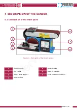
Страница 11: ...PTION OF THE SANDER 4 1 Description of the main parts Figure 1 Main parts of the Bench sander 1 Machine body 5 Abrasive disc 2 Work table 6 ON OFF buttons 3 Stop piece support 7 Piece orientation bracket 4 Abrasive belt 3 5 7 2 4 1 4 f e r v i c o m ...

Страница 12: ... mani all utensile mentre è in movimento Non regolare la macchina mentre è in funzione Indossare sempre occhiali e guanti antinfortunistici adeguati Scollegare la macchina dall alimentazione elettrica in caso di riparazioni o regolazioni Non indossare abiti ampi cravatte collane bracciali e raccogliere i capelli lunghi perché potrebbero essere agganciati alle parti in movimento Non rimuovere o dis...

Страница 13: ...È VIETATO ESEGUIRE LAVORI SU APPARECCHIATURE ELETTRICHE SOTTO TENSIONE EVENTUALI DEROGHE DEVONO ESSERE AUTORIZZATE DAL CAPO RESPONSABILE IN CONDIZIONI DI PARTICOLARE PERICOLO DEVE ESSERE PRESENTE UN ALTRA PERSONA OLTRE A CHI ESEGUE IL LAVORO INIZIARE I LAVORI SOLO AD AVVENUTA ATTAZIONE DELLE MISURE DI SICUREZZA In ottemperanza al Dgs 81 08 relativo alla prevenzioni infortuni f e r v i c o m ...

Страница 14: ...g ties necklaces bracelets and tie up long hair because it could catch on moving parts Do not remove or disable any safety devices For further information on safety please consult the instruction manual ATTENZIONE È VIETATO ESEGUIRE LAVORI SU APPARECCHIATURE ELETTRICHE SOTTO TENSIONE EVENTUALI DEROGHE DEVONO ESSERE AUTORIZZATE DAL CAPO RESPONSABILE IN CONDIZIONI DI PARTICOLARE PERICOLO DEVE ESSERE...

Страница 15: ...ered and both of the abrasive tools are set in rotation belt and disc Conversely the red button 0 is used to switch off the sander By pressing this button the electric motor is disconnected from the power supply and both of the abrasive tools stop rotating belt and disc Figure 4 Start and stop buttons Risk of abrasion After pressing the stop switch 0 the abrasive tools continue to rotate by inerti...

Страница 16: ...tive ring In the event of malfunction or breakdown the sander is equipped with power cable and plug with grounding conductor which provides a path of least resistance for electric current and reduces the risk of electric shock The plug must be plugged into an appropriate outlet earthed in accordance with current regulations Extension cables must be of a section equal to or greater than the power c...

Страница 17: ...brasive tools Checking the safety devices Each time the sander is used check that the guards function and are positioned properly In the event of damage and or breakage do not use the machine Use of PPE In any case ALWAYS use appropriate personal protective equipment such as Gloves Goggles or face shields Overalls or aprons Safety shoes Figure 5 Personal Protective Equipment f e r v i c o m ...

Страница 18: ...able using the 3 fastening screws and the washers supplied as shown in Figure 6 To do this use a hex wrench 3 Turn the table so that the support and the relative fastening screws are facing down and then position the table in such a way that the pin D present in the support is aligned with the hole on the machine body as shown in Figure 7 4 Insert the locking lever E of the table with its relative...

Страница 19: ...ly tightening the lever E adjust the distance between the edge of the table and the abrasive disc In this regard insert a feeler gauge of approximately 2 mm between the two parts or any item with this thickness Table support Rotation pin Base Washer Table lock D E f e r v i c o m ...

Страница 20: ...n the workbench of any materials and dirt that may be present Drill two fastening holes in a flat solid and strong workbench or on another surface with similar characteristics For the dimensions and position of the fastening holes see the Figure Figure 9 Position of the fastening holes 1 Place the machine on the bench so as to line up the fastening holes in the base with those in the bench Sander ...

Страница 21: ... fastening holes In the case of using a steel bench it is advisable to place between the sander and the supporting surface a layer of material which is able to reduce the vibrations produced Installation of the machine Do not install the Machine outdoors to avoid deformation loss of functionality and damage to the electrical control circuit f e r v i c o m ...

Страница 22: ...d from the machine 2 Unscrew the fastening screws of the protective casing over the lower part of the disc then remove the casing 3 Detach part of the rear protective sheet and attach the abrasive disc to the backing pad so as to align the outer perimeter of the disc with that of the backing pad figure 11 Remove the protective sheet a little at a time and then press the disc onto the pad 4 Attach ...

Страница 23: ...g the belt so as to respect the proper direction of rotation Rotation direction Before beginning installation abrasive belt always check that the rotation direction is correct as indicated by the arrow on the internal part 1 Move the lever to the right on the side opposite to the electric motor to release the tension of the abrasive belt as indicated in figure 12 then extract the worn belt Figure ...

Страница 24: ...he abrasive disc turn the alignment knob N clockwise with a turn Figure 14 and then restart the machine for a few seconds and see if the belt still slips 6 Conversely if the belt slips in the opposite direction to the abrasive disc turn the alignment knob N anti clockwise with a turn Figure 14 and then restart the machine for a few seconds and see if the belt still slips Obviously the belt is prop...

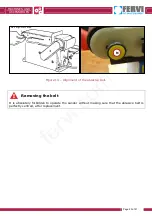
Страница 25: ... of 41 Figure 14 Alignment of the abrasive belt Removing the belt It is absolutely forbidden to operate the sander without making sure that the abrasive belt is perfectly centred after replacement Belt alignment knob N f e r v i c o m ...

Страница 26: ...with an angle up to 45 Using the machine The Sander must only be used with belts and discs that are suitable for the type of machine and the type of material to be processed Risk of Abrasion and Accident Before using the machine make sure that it is securely and firmly fixed to the work surface to prevent unwanted movement or a loss of stability Wear appropriate personal protective equipment PPE s...

Страница 27: ...tarting the sander Conversely to stop the sander press the red button marked with the symbol 0 as shown in Figure 15 By pressing this button the electric motor is disconnected from the power supply and both of the abrasive tools are stopped belt and disc Figure 15 Stopping the sander Risk of abrasion After pressing the stop switch 0 the abrasive tools continue to rotate by inertia for a few moment...

Страница 28: ...esting against the stop piece support without touching the belt with your fingers or hands Figure 17 Figure 16 Sanding surfaces 4 Move the workpiece gently during sanding paying close attention when working with very thin pieces 5 After processing turn off the machine by pressing the red stop button see Figure 15 If very long pieces need to be sanded the stop piece support will have to be removed ...

Страница 29: ...d on the table then push the end surface of the workpiece gently against the abrasive disc figure 17 4 Slightly move the workpiece during sanding from the left to the centre of the disc taking great care not to touch the disc with your fingers or hands 5 After processing turn off the machine by pressing the red stop button see Figure 15 Figure 17 Sanding ends Risk of Abrasion and Accident Never in...

Страница 30: ...ry to adjust the angle of the goniometer from 0 to 60 To perform the sanding of angled surfaces proceed as follows 1 Adjust the angle of the goniometer using the relative knob fig 19 2 Proceed with the sanding operation as previously described in this section Figure 18 Adjusting the goniometer f e r v i c o m ...

Страница 31: ...ith the idle roller Figure 20 3 Slightly move the workpiece during sanding taking great care not to touch the disc with your fingers or hands 4 After processing turn off the machine by pressing the red stop button see Figure 16 Figure 19 Sanding of curved surfaces Risk of knocks and accidents Do not sand the end of the piece by resting it on the idle roller This could cause the ejection of the pie...

Страница 32: ...d as follows 1 Loosen the locking lever E by turning it anti clockwise Figure 21 2 Tilt the table according to the angle desired checking the angle against the graduated scale Figure 21 then re lock the table by tightening the lever E clockwise Figure 20 Tilting of the work table Unexpected start up Before starting the adjustment of the work table always disconnect the machine from the power outle...

Страница 33: ...re 22 For this purpose use an Allen wrench 6 mm Figure 21 Belt holder frame locking screw 2 Lift and rotate the belt holder frame so as to move the belt into a vertical position Figure 22 3 Remove the stop piece support 4 Tighten the locking screw R of the belt holder frame turning it clockwise For this purpose use an Allen wrench 6 mm 5 Completely unscrew the work table locking lever E extract th...

Страница 34: ...belt inserting the pin D and the lever E in the auxiliary holes present on the side of the belt holder frame as shown in figure 24 Figure 23 Worktable assembly 7 Tighten the working table locking lever E turning it clockwise Allen screw Table locking lever Table support Auxiliary assembly holes Washer Pulley guard f e r v i c o m ...

Страница 35: ...om the power outlet This is so that there is no risk of electric shock Only use a warm damp cloth to clean the body of the machine and other external parts Cleaning the machine DO NOT use detergents or any solvents the plastic parts are easily damaged by chemical agents Periodically check for wear on the abrasive belts and discs taking care to replace them if there are cracks defects and or detach...

Страница 36: ...rease the tension Figure 25 5 Tighten the locking screws and not knock the belt 6 To check the tension tighten the belt between two fingers it should yield about 5 6 mm Figure 25 If the belt is loose or too tight it can cause excessive noise motor overload or premature ageing of the belt Figure 24 Checking and replacing the drive belt Entanglement Before removing the belt protection guard turn off...

Страница 37: ...ntact the service department The motor slows down during sanding A The belt is too tight B The piece is being pushed too much A Reduce the belt tension B Exert a lower pressure The belt slips on the rollers A The position of the rollers is not properly adjusted A Increase the tension of the belt and adjust the centring The wood pieces to be sanded burn A The disc or belt has wood residues A Replac...

Страница 38: ...cialist centre for the collection of metallic materials The structure of the sander is made of steel the belts and discs are made of abrasive material some of the seals are made of polymeric material In this regard divide the materials according to their nature employing specialist companies which are authorised for their disposal in accordance with the requirements of law f e r v i c o m ...

Страница 39: ...MACHINES AND ACCESSORIES Page 39 of 41 14 ELECTRIC CIRCUIT Magnetic switch Motor cable Motor Power cable f e r v i c o m ...

Страница 40: ...MACHINES AND ACCESSORIES Page 40 of 41 15 EXPLODED VIEW AND SPARE PARTS f e r v i c o m ...

Страница 41: ...p bearing 0505 50 Screw M5x0 8 25 0505 16 Bearing with felt washer 0505 51 Support bearing 0505 17 Spacer bearing 0505 52 Belt cover 0505 18 Switch housing 0505 53 Support frame 0505 19 Locking washer M5 0505 54 Square nut M8x1 25 0505 20 Screw M5x0 8 16 0505 55 Rubber buffer 0505 21 Switch 0505 56 Hex head screw M8x1 25 25 0505 22 Switch hook 0505 57 Ball bearing 0505 23 Condenser 0505 58 Sealing...

Отзывы: