24
CONNECTIONS
Hydraulic connections
To design properly the hydraulic system respect the local safety
regulations in force.
It is always necessary to guarantee an appropriate water flow
through the plate heat exchanger of the unit even if is installed,
as standard, a differential pressure switch that stops the unit if
the water flow rate is too low.
Moreover all the unit are equipped with an antifreeze electrical
heater on the plate heat exchanger.
To adjust the water flow rate through the heat exchanger modify
the speed of the pump by means of the 3 speed selector (if
present). For a more accurate adjustment it is reccomended the
installation of a valve on the outlet of the circuit.
It is also reccomended to install a filter (with mesh Ø holes
≤ 500 µm) on the inlet of each circuit, otherwise the warranty
will be invalidated . The filter fulfil the function to block the
entrance of foreign substances (chips, machining debris . . .)
contained inside the hydraulic circuit, avoiding the heat
exchanger from clogging and from the possibility to freeze
up (and sebsequently burst) .
If as “Storing and pumping module” option has been chosen
“Standard pump” or “High head pump” or "Modulating pump" or
"Tank and standard pump" or "Tank and high head pump" or
"Tank and modulating pump", the hydraulic circuit is equipped
with an expansion vessel. To mantain the circuit under pressure
a self-filling group, that automatically fills the circuit, can be
installed.
Hydraulic circuit cleaning
Before connecting the unit ensure a proper plant washing using
clean water, filling and discharging the plant several times and
cleaning the filters installed on the unit inlet.
Verify by qualified personnel the quality of the water or of the
brine solution used. Avoid in particular the presence of inorganic
salts, bioburden (algae), suspended solids and dissolved oxy-
gen.
Suggestions for the hydraulic plant realization
Prepare the pipes with the minimum possible number of bends
in order to minimize pressure losses, and suitably support them
to prevent excessive stresses at the connections of the unit.
Install shut-off valves near the components that need
maintenance, to allow their replacement without having to drain
the system.
Provide manual or automatic valves in the highest part of the
circuit to vent the air.
Make sure there are no leaks before insulating the pipes and
filling the system.
In order to avoid condensate generation, insulate all the pipes
using steam barrier type material.
Finned coil condensate drainage
The condensate generated by the finned coil in heating mode is
collected in the tray obtained in the basement of the unit and can
be drained connecting a pipe to the fitting supplied as standard
with all the heat pump units.
Precautions during winter time
During winter, in case of plant stops, the water could frreze and
damage the plate heat exchanger of the unit and other plant
components. To prevent these problems threee solutions are
possible :
1. Completely drain the plant, paying attention to the plate heat
exchanger drainage (open all air vents to facilitate the opera-
tion).
2. Use brine solutions considering that, according to the glycol
quantity added, the performances of the unit have to be cor-
rected.
3. Keep the unit electrically powered during the whole winter.
The plate heat exchanger is protected by the antifreeze elec-
trical heater supplied as standard on the heat exchanger.
The circulating pump is activated by the controller of the unit
according to the outdoor air temperature in order to protect
the pipes. For the unit with the tank (VA) is available, as an
accessory, an antifreeze electrical heater that avoids ice ge-
neration inside the tanked and is activated by the controller
of the unit together with the antifreeze electrical heater of
the plate heat exchanger. The integrative electrical heaters,
if present, also carry out the antifreeze function.
Expansion vessel setting
The precharge pressure of the expansion vessel must be
adequate to the total volume of the hydraulic circuit to which the
unit is connected.
The factory setting is the minimum value necessary to avoid the
presence of zones with a negative relative pressure inside the
hydraulic circuit and the risk of pump cavitation, supposing that
no parts of the plant are placed at a higher level than the one at
which the unit is installed. In that case the precharge pressure
must be increased proportionally to the elevation of the highest
part of the plant according to the following relation :
p
VE
= p
VE-std
+ H
max
/ 9,81
p
VE
: expansion vessel precharge pressure [bar g]
H
max
: elevation of the highest part of the plant referred to the
unit installation level [m]
The maximum value of the precharge pressure is equal to the
safety valve pressure set.
Increasing the precharge pressure, the maximum plant volume
supported by the expansion vessel supplied with the unit is
reduced :
V
I
= V
VE
· C
e
· [ 1 - ( 1 + p
VE
) / ( 1 + p
VS
) ]
V
I
: plant volume supported by the expansion vessel [l]
V
VE
: expansion vessel volume [l]
C
e
: expansion coefficient
p
VS
: safety valve pressure set [bar g]
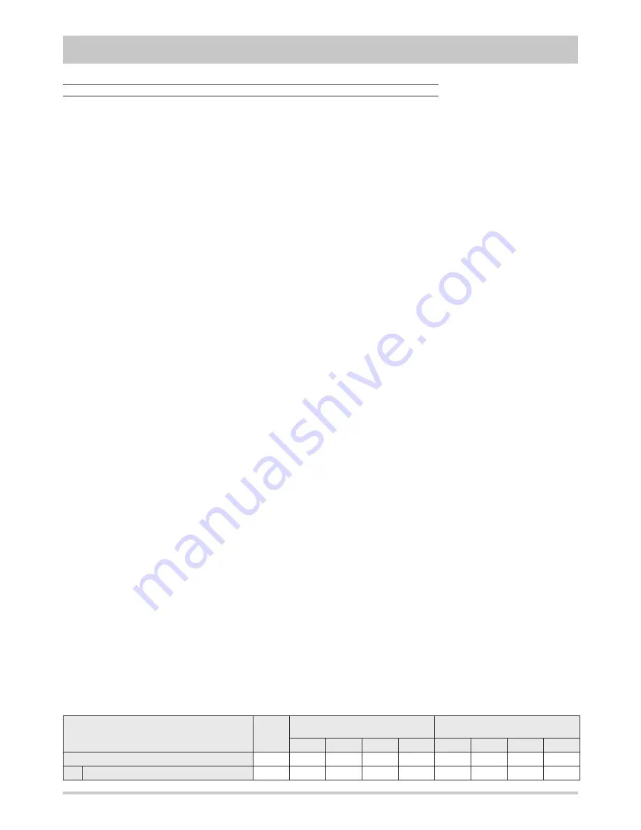
Water
Ethylene glycol
(percentage by volume)
Propylene glycol
(percentage by volume)
10%
20%
30%
40%
10%
20%
30%
40%
Freezing temperature [°C]
0
-3,8
-8,9
-15,7
-24,9
-3,4
-7,4
-13,1
-21,5
C
e
Plant side (T
min
= 5°C , T
max
= 60°C)
58,63
47,80
45,24
42,82
40,61
45,47
39,96
35,82
32,88
Содержание RMA series
Страница 40: ...40...
Страница 41: ...41 DECLARATION OF CONFORMITY...
Страница 42: ...42...
Страница 43: ...43...


