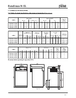
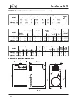
Ferroli RENDIMAX N EL Скачать руководство пользователя страница 20

Rendimax N EL

20

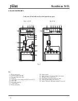
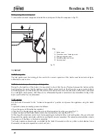
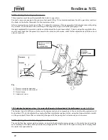
9.02 opening the control panel

To access the electrical components inside the control panel, follow the sequence in fig. 10.

fig. 10

10. SET-UP

10.01 fi rst ignition

The first ignition and the training of the user for the correct operation of the boiler must be carried out by an 
authorised service centre.

10.02 checks to be performed upon fi rst ignition

During the first ignition of the boiler, it is important to check that the on-off valves between the boiler and the 
heating system are open; that the heating circuit is filled and vented of air; that there are no gas or water leaks in 
the heating system or in the boiler; that the electrical connections are correct and that the earth cable is connected 
to an adequate earth system; that there are no inflammable liquids or materials in the immediate vicinity of the 
boiler; and that the flue is not blocked.
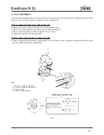
10.03 ignition

Set the boiler thermostat to the “minimum temperature” position, and power the appliance using the boiler 
switch.
To ignite the burner assembly, proceed as follows:
• Open the gas cock (fitted by the installer);
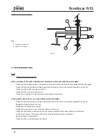
• Vent the air in the gas pipes using the air vent fitted upstream from the gas valve (fig. 11).
• Adjust the knob on the boiler thermostat to the desired value (not less than 50 °C.).
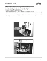
At this stage the electronic control unit starts operating and will pilot, after a set waiting time, the gas valve and 
the spark to the ignition electrode, which in turn will light the burner assembly. The ionisation electrode then checks 
the presence of the flame in the burner assembly.
The boiler operates automatically, controlled by the boiler thermostat and/or any other control devices (room 
thermostat, electronic temperature control unit, etc.).

3

1

5

2

4

Key


1

 Boiler cover


2

  Protective cover fastening screw


3

  Wiring protective cover


4

  Fastening plate and screw


5

 Control panel

Содержание RENDIMAX N EL

Страница 1: ...Nr A 9504 A 0085 AQ 0766 RENDIMAX N EL gas fired cast iron boiler for central heating with electronic ignition and flame control OPERATING INSTALLATION AND MAINTENANCE INSTRUCTIONS cod 3543742 3 05 2...

Страница 2: ......

Страница 3: ...e or a suitable isolating device In the event of malfunction or faulty operation deactivate the appliance Do not attempt to repair or carry out any other operation on the appliance directly Contact qu...

Страница 4: ...n 7 4 Checks and maintenance 8 INSTALLATION AND MAINTENANCE INSTRUCTIONS 5 Description of the boiler 9 6 Main components 10 7 Technical specifications 11 8 Installation and safety devices 16 9 Electri...

Страница 5: ...ly installation conversion to other type of gas commissioning and maintenance of the boiler must be performed by specialist Companies following all the relative technical requirements and standards Th...

Страница 6: ...assembly 8 Control panel 9 Burner assembly Front view of the boilers with control panel cover open 5 3 11 10 14 15 13 9 6 7 12 8 1 2 4 8 5 3 11 10 13 1 2 10 Boiler switch 11 Reset button for electroni...

Страница 7: ...electronic control unit 11 Fig 1 is on wait around 10 seconds and then press the reset button The control unit is reset and will repeat the ignition cycle Note In the event of power failure the burner...

Страница 8: ...ot clean the appliance and or its parts with easily inflammable substances e g petrol alcohol etc Do not leave containers with inflammable substances in the room where the appliance is installed 4 02...

Страница 9: ...able speed pump expansion vessel and safety valve The boilers are manufactured as standard for operation on natural gas G20 The appliance can be converted from operation on natural gas to lpg G31 refe...

Страница 10: ...Reset button for electronic flame control unit 12 Electronic flame control unit 13 Safety thermostat with automatic reset 14 Hheating system pump pv version 15 Cap on fitting for filling the system p...

Страница 11: ...00 kW 12 7 18 4 23 0 27 6 kcal h 11 000 15 800 19 800 23 800 Number of sections 3 4 5 6 Boiler water content lt 7 3 9 0 10 7 12 4 Max working pressure bar 6 6 6 6 injector mm 2 45 2 35 2 35 2 35 Nomin...

Страница 12: ...800 19 800 Number of sections 3 4 5 Boiler water content lt 7 3 9 0 10 7 Max working pressure bar 6 6 6 injector mm 2 45 2 35 2 35 Nominal pressure mbar 13 0 15 2 14 2 injector mm 1 55 1 50 1 50 Nomi...

Страница 13: ...the output variation feature governed by the relative standards the boiler maintains near constant thermal efficiency values and combustion characteristics The instructions for adjusting the gas valve...

Страница 14: ...em models 16 23 30 pv The difference between the supply and return temperature in the central heating system can be adjusted using the speed selector switch on the pump In this way the flow rate and d...

Страница 15: ...tem water flow rate 7 07 Residual discharge head available to the heating system models 16 23 30 PV Note The diagram in fig 7 refers to the maximum heating pump discharge head flow rate with the speed...

Страница 16: ...fitted Check any existing flues to make sure they have been carefully cleaned as any scale flaking off the side walls during operation may block the passage of the flue gas creating extremely dangerou...

Страница 17: ...eck that on exceeding the pressure value indicated above the safety valve intervenes to discharge the excess water 8 11 Temperature limiting device safety thermostat with automatic reset The function...

Страница 18: ...s components inside the control panel see paragraph 9 02 Note If replacing the power cable only use HAR H05 VV F 3x0 75 mm2 cables with a maximum external dia meter of 8 mm Diagram of electrical conne...

Страница 19: ...ting from the failure to electrically earth the boiler 24 Ignition electrode 32 Heating system pump models 16 23 30 pv 44 Gas valve 49 Safety thermostat 63 Boiler thermostat 72 Room thermostat not sup...

Страница 20: ...nity of the boiler and that the flue is not blocked 10 03 ignition Set the boiler thermostat to the minimum temperature position and power the appliance using the boiler switch To ignite the burner as...

Страница 21: ...it and the heating system for tightness Check the correct operation of the boiler by effecting ignition and shut down tests using the regulation thermostat Check on the rear wall of the boiler at the...

Страница 22: ...to the instructions provided in paragraph 8 06 In the case of an open vessel system simply check the water level periodically Decrease Increase 11 03 adjusting the heating system power This procedure...

Страница 23: ...ig 12 Using a small screwdriver adjust the ignition step to lpg Replace the small cap 3 on the regulator 12 02 to change from lpg g31 to natural gas g20 Follow the operations described in paragraph 12...

Страница 24: ...eration of the boiler Check that the connecting pipe between the boiler and flue is perfectly sealed at the joints Check that in the absence of a flame in the burner assembly the appliance shuts down...

Страница 25: ...14 Disconnect the cables from the electrode assembly Unscrew the four screws which fasten the gas supply pipe upstream from the gas valve Unscrew the two nuts which fasten the door of the combustion c...

Страница 26: ...the boiler is properly earthed Check that the gas valve is powered Check the connections to the ignition and ionisation electrodes In the ignition phase there is no spark between the electrodes Check...

Страница 27: ...the heating system is too high or too low Check the operation of the regulation thermostat Check that the pump is not blocked Check that the circulating pump is adequately rated for the system Explosi...

Страница 28: ...FERROLI S p A Via Ritonda 78 a 37047 San Bonifacio Verona ITALY www ferroli it...

Отзывы: