Rendimax N EL
18
9. ELECTRICAL CONNECTIONS
9.01 electrical connection
The boiler must be connected to a single-phase, 230 volt - 50 hz (phase/neutral) power supply, with 3 a max fu-
ses, and a bipolar switch with minimum contact opening of at least 3 mm fitted between boiler and the source
of power. It is important to always properly earth the boiler. . The control panel is fitted with a terminal block for
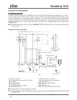
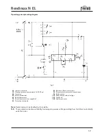
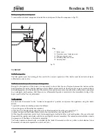
connecting the boiler to any room thermostats or electronic temperature control units present (follow the wiring
diagrams in figs. 8 and 9). To access this terminal block and the various components inside the control panel, see
paragraph 9.02.
Note
If replacing the power cable, only use “
HAR H05 VV-F
” 3x0.75 mm
2
cables, with a maximum external dia-
meter of 8 mm
Diagram of electrical connections
fig. 8
Note
Dashed wiring to be handled by the installer
N.B.
The manufacturer declines all liability for damage to persons or things resulting from the failure to electrically
earth the boiler.
24
Ignition electrode
32
Heating system pump (models 16-23-30 pv)
44
Gas valve
49
Safety thermostat
63
Boiler thermostat
72
Room thermostat (not supplied)
82
Detection electrode
83
Electronic flame control unit
92
Flue gas thermostat with manual reset
98
Boiler switch
129
Reset button with pilot light
159
Test knob
160
Auxiliary contact
242
Connector for thermostatic control unit
Содержание RENDIMAX N EL
Страница 2: ......
Страница 28: ...FERROLI S p A Via Ritonda 78 a 37047 San Bonifacio Verona ITALY www ferroli it...

