


OPTIMAX HE 31 S
32
Cod. 3540F441 - 03/2007 (Rev. 01)
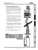
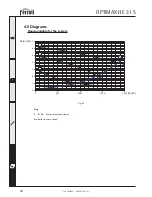
4.3 Hydraulic diagram
fig. 28
56
44
14
32
11
10
7
241
246
36
186
161
201
278
193
154
16
Key
7
Gas
inlet
10
CH
flow
11
CH
return
14
Pressure Relief valve
16
Premix fan assembly
32
Pump
36
Automatic air vent
44
Gas
valve
56
Expansion
vessel
154
Condensate outlet pipe
161
Heat
exchanger
186
Return
sensor
193
Siphon
201
Fan
Venturi
241
Automatic
by-pass
246
System pressure sensor
278
Double sensor ( Heating)
Содержание OPTIMAX HE 31 S
Страница 36: ......