


OPTIMAX HE 31 S
17
Cod. 3540F441 - 03/2007 (Rev. 01)
* = between
10 e 60 mm
* = between
10 e 60 mm
80
95
95
50*
80
95
30
50*
Standard 1KWMA53A
Flue kit
232
218
30
P
125
S
D
S 50*
L
30
95
S
50*
P
95
L
D
S
232
218
156
Drill the wall 10÷20 mm
more than the
pipe diameter
218
232
156
Drill the wall 10÷20 mm
more than the pipe diameter
Install level
Install level
Install level
Install level
eco
comfort
reset
1
2
3
4
0
BAR
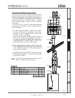
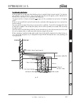
Side view
View from above
fig. 17a
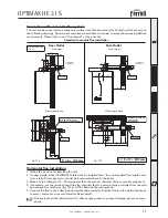
Side Outlet
fig. 17b
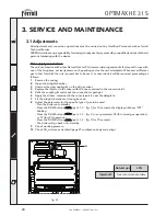
Front view
View from above
P = S + 145 mm
Rear Outlet
L = S + D + 203 mm
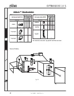
Connection with concentric flue system
The unit can be connected to a concentric air/flue duct with a Horizontal or Vertical outlet as shown on
the following drawings. Numerous accessories are available on request to meet the various installation
requirements. Please refer to our “flue manual” or the price list.
Standard concentric flue installation
Horizontal flue installation
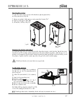
1. Define the position for installing the unit.
2. If using standard flue (1KWMA53A) this must be installed level, for non-standard flue lengths over
1mtr a fall of 3 mm per metre should be incorporated back to the boiler.
3. Make a hole of diameter 10 - 20 mm greater than the nominal diameter of the concentric pipe used.
4. If necessary, cut the terminal length to size, ensuring that the external pipe protrudes from the wall
by between 10 and 60 mm (fig. 17a and 17b). Remove the cutting burrs.
5. Connect the flue to the boiler, positioning the seals correctly. Seal the flue into the wall with silicone
or sand + cement and cover with wall seals provided.
Flue seals should be lubricated with a silicone type grease to prevent damage (grease not sup-
plied)
Содержание OPTIMAX HE 31 S
Страница 36: ......