


in the event of a minor impact, the airbag ECU does not deploy the airbags;
in the event of a more severe impact, the ECU deploys the passenger airbag in reduced force mode;
in the event of a very severe impact, the ECU deploys the passenger airbag in full force.
Lateral airbag modules
The vehicle is equipped with two lateral airbags, one located inside the driver side door and the other inside
the passenger side door.
The lateral airbags are controlled by an ECU, which deploys them in the event of a lateral impact of sufficient
severity.
The deployment of the lateral airbags is not influenced by the stature or weight of the occupant.
In the event of a lateral impact of a severity exceeding the threshold set in the ECU, the ECU sends a signal
deploying the pretensioner, the lateral airbag on the side of the collision and the active rollbars. The latter
is a precautional measure as deformation to the bodyshell caused by the impact may impede the
subsequent deployment in the event of the vehicle rolling over.
The airbag begins to inflate, breaking the trim panel along a predetermined break line, and inflates fully within
a few hundreds of a second.
Once inflated, the lateral airbag acts as a protective cushion between the head of the driver/passenger and
any structures penetrating the passenger compartment from the exterior, which could cause injury.
The airbag deflates immediately afterwards.
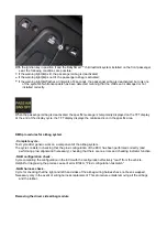
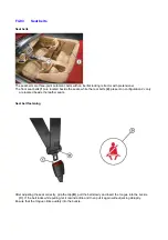
Deactivating the passenger airbag (FROM M.Y. 2010)
The passenger airbag in the vehicle may only be deactivated by using a specific FERRARI child seat.
The specific child restraint systems have been designed to work in conjunction with the BabySmart™
automatic child seat detection system (CPOD) for the front passenger seat of this vehicle.
The specific child seats function like other child safety seats, except for the fact that they are designed to
automatically deactivate the passenger airbag in vehicles equipped with the “BabySmart™ system”.
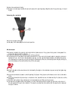
The specific child seats are equipped with two transponders, which are identified and detected by special
transmitters installed in the front passenger seat.
If the specific child restraint system is installed correctly on the front passenger seat, the transponders are
detected by the transmitters and the front passenger airbag is deactivated.
The full protective function of the restraint system is only ensured if the restraint system itself is
installed and used correctly.
DO NOT place electronic devices (functioning laptop computers, mobile phones, cards with
transponders etc.) on the front passenger seat in a vehicle equipped with the BabySmart™ system,
as signals emitted by electronic devices may interfere with the automatic child seat detection
system sensors, resulting in system malfunctions and causing the front passenger airbag to fail to
be activated and deactivated correctly.
Содержание California
Страница 19: ...Z Tyre type and pressure label ...
Страница 20: ...04 02 Assembly number Assembly number A Assembly number label ...
Страница 21: ...04 03 Chassis number Chassis number B Punched chassis number ...
Страница 22: ...04 04 Engine type and number Engine type and number C Punched engine type and number ...
Страница 23: ...04 05 Chassis number Chassis number D Chassis number ...
Страница 24: ...04 06 Gearbox type and number Gearbox type and number E Gearbox type and number plate ...
Страница 25: ...04 07 Vehicle identification Vehicle identification K VIN label Vehicle Identification Number ...
Страница 26: ...04 08 Tyres Tyres F Tyre pressure monitoring system identifier label Z Tyre type and pressure label ...
Страница 28: ...04 10 Fuel Fuel I Fuel label ...
Страница 29: ...04 11 Paintwork Paintwork L Paintwork label ...
Страница 30: ...04 12 Emissions control Emissions control M Emissions control data label ...
Страница 31: ...04 13 Airbag Airbag N Do not install child seat on passenger seat label ...
Страница 32: ...04 14 Airbag Airbag O Airbag maintenance label ...
Страница 33: ...04 15 Airbag Airbag P Airbag warning label ...
Страница 43: ...Fluids and lubricants table Model Fluids and lubricants table Download ...
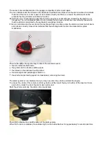
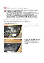
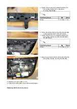
Страница 71: ...Screw the cap A back on tightly ...
Страница 104: ...Connect the battery F2 01 ...
Страница 118: ...Vehicle Setup Parameter Check Form Model Vehicle Setup Parameter Check Form Download ...
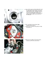
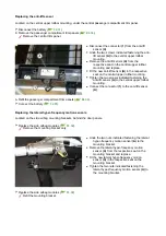
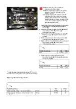
Страница 224: ...Undo the screws indicated Retrieve the brackets E Undo the screws indicated Undo the screws indicated ...
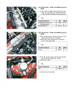
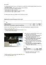
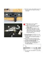
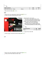
Страница 259: ...Replace the gasket 11 Replace the gasket 10 Undo the screws indicated Remove the tensioner F complete with mount ...
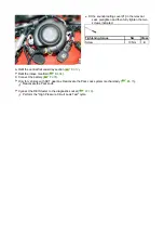
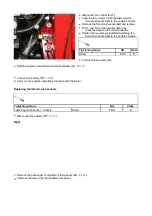
Страница 286: ...Tighten the screws indicated Tightening torque Nm Class Screw 9 Nm B Connect the connector 9 Connect the connector 8 ...
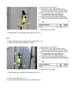
Страница 518: ...Check the Shell Transaxle 75W 90 GL5 gear oil level A3 02 Check that there is no leakage from the drain plugs ...
Страница 520: ...A DCT gearbox clutch oil tank and clutch oil pump B Clutch oil pipes C Clutch oil radiator ...
Страница 623: ...CCM Brake Disc Wear Form Model All Models CCM Brake Disc Wear Form Download ...
Страница 1040: ...Undo the screws indicated Remove the inner handle A Undo the screws indicated Undo the screws indicated ...
Страница 1068: ...A External light switch B TFT display controls C Parking brake controls D Engine compartment lid release lever ...
Страница 1069: ...E Instrument panel F NIT G Hazard warning light button H Cup holder Instruments and controls on steering wheel ...
Страница 1070: ...A Horn button B Engine start button C Manettino ...
Страница 1102: ...Perform the respective cycle with the DEIS diagnostic tester ...
Страница 1144: ...Connect the battery F2 01 ...
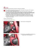
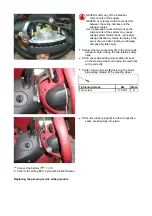
Страница 1220: ...Precautions and guidelines for using the RHT retractable hard top ...
Страница 1328: ...Refit the Tonneau Cover E6 06 Refit the luggage compartment lid E3 02 Connect the battery F2 01 ...
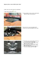
Страница 1332: ...Detach the front mounts of the headliner trim Detach the rear mounts of the headliner trim Undo the headliner fastener screw ...
Страница 1334: ...Undo the indicated fasteners Retrieve the indicated shims Release the clip 1 ...
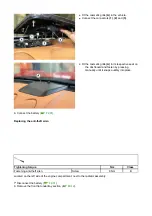
Страница 1335: ...Remove the indicated clip Undo the indicated screw Undo the screws indicated ...
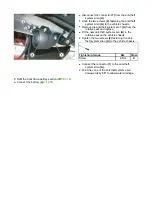
Страница 1338: ...Tighten the screws indicated Tightening torque Nm Class Screw 4 Nm B Refit the indicated clip Attach the clip 1 ...
Страница 1379: ...Remove the pad B and replace Fit and fasten the new pad B pressing it by hand Fit the trim A correctly ...
Страница 1398: ...Above 35 C D8215 Spot Repair D8215 Extended D886 for detailed information see technical datasheet 171 Deltron D8105 ...
Страница 1452: ...Refit the rear wheelhouses E3 05 Connect the battery F2 01 ...
Страница 1453: ...F2 07 Lights Diagnosing condensation in headlamps ...
Страница 1454: ...Whenever condensation is found in a headlamp please perform the checks and tests indicated above before starting any work ...
Страница 1561: ...Ss Sensor signal λ Lambda ratio excess g Rich mixture M Lean mixture ...
Страница 1570: ...Refit the DCT gearbox C2 03 Connect the battery F2 01 ...
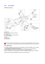
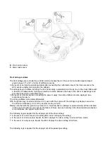
Страница 1612: ...F4 02 Airbag Airbag system layout A Driver side airbag module B ECU C Side airbag module D Passenger side airbag module ...
Страница 1656: ...G Heater evaporator H Pollen filter I Air vents M Expansion valve ...
Страница 1677: ...Refit the front wheelhouses E3 05 ...
Страница 1686: ...Refit the caps 1 Refit the engine compartment cosmetic shields E3 13 ...