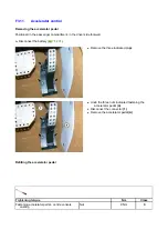


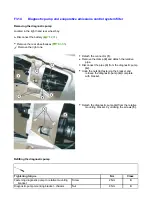


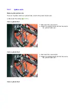

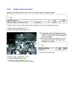

Replacing the secondary air valve
Secondary air valve - exhaust manifold connector
pipe
Screw 8
Nm
B
Tightening torque
Nm
Class
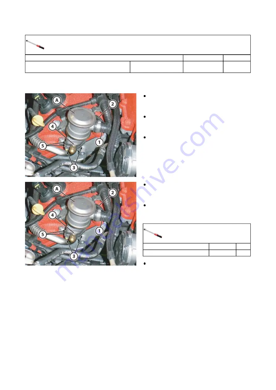
The following procedure is for the replacement of the right hand secondary air valve; the procedure for the
left hand one is identical.
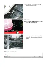
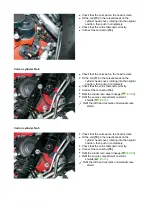
Detach the pipe
(1)
, removing the relative clamp
and the rubber connector pipe
(2)
leading to
the vacuum accumulator tank, from the
secondary air valve
(A)
.
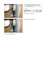
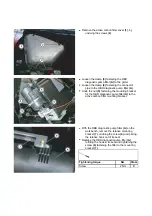
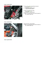
Undo the two screws
(3)
fastening the secondary
air valve
(A)
to the connector pipe leading to
the exhaust manifold and to the relative
mounting bracket.
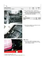
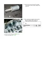
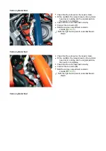
Remove the secondary air valve
(A)
retrieving
the two seals
(5)
and the shim
(4)
.
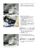
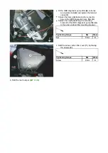
Fit the secondary air valve
(A)
in the relative seat
on the pipe leading to the exhaust manifold,
after installing the two new seals
(5)
and the
shim
(4)
between the parts.
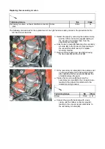
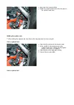
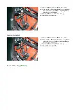
Tighten the two screws
(3)
fastening the
secondary air valve
(A)
to the connector pipe
leading to the exhaust manifold and to the
relative mounting bracket.
Tightening torque
Nm
Class
Screw 8
Nm
B
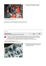
Connect the pipe
(1)
, fastening with a new
clamp, and the rubber connector pipe
(2)
leading to the vacuum accumulator tank, to
the secondary air valve
(A)
.
Содержание California
Страница 19: ...Z Tyre type and pressure label ...
Страница 20: ...04 02 Assembly number Assembly number A Assembly number label ...
Страница 21: ...04 03 Chassis number Chassis number B Punched chassis number ...
Страница 22: ...04 04 Engine type and number Engine type and number C Punched engine type and number ...
Страница 23: ...04 05 Chassis number Chassis number D Chassis number ...
Страница 24: ...04 06 Gearbox type and number Gearbox type and number E Gearbox type and number plate ...
Страница 25: ...04 07 Vehicle identification Vehicle identification K VIN label Vehicle Identification Number ...
Страница 26: ...04 08 Tyres Tyres F Tyre pressure monitoring system identifier label Z Tyre type and pressure label ...
Страница 28: ...04 10 Fuel Fuel I Fuel label ...
Страница 29: ...04 11 Paintwork Paintwork L Paintwork label ...
Страница 30: ...04 12 Emissions control Emissions control M Emissions control data label ...
Страница 31: ...04 13 Airbag Airbag N Do not install child seat on passenger seat label ...
Страница 32: ...04 14 Airbag Airbag O Airbag maintenance label ...
Страница 33: ...04 15 Airbag Airbag P Airbag warning label ...
Страница 43: ...Fluids and lubricants table Model Fluids and lubricants table Download ...
Страница 71: ...Screw the cap A back on tightly ...
Страница 104: ...Connect the battery F2 01 ...
Страница 118: ...Vehicle Setup Parameter Check Form Model Vehicle Setup Parameter Check Form Download ...
Страница 224: ...Undo the screws indicated Retrieve the brackets E Undo the screws indicated Undo the screws indicated ...
Страница 259: ...Replace the gasket 11 Replace the gasket 10 Undo the screws indicated Remove the tensioner F complete with mount ...
Страница 286: ...Tighten the screws indicated Tightening torque Nm Class Screw 9 Nm B Connect the connector 9 Connect the connector 8 ...
Страница 518: ...Check the Shell Transaxle 75W 90 GL5 gear oil level A3 02 Check that there is no leakage from the drain plugs ...
Страница 520: ...A DCT gearbox clutch oil tank and clutch oil pump B Clutch oil pipes C Clutch oil radiator ...
Страница 623: ...CCM Brake Disc Wear Form Model All Models CCM Brake Disc Wear Form Download ...
Страница 1040: ...Undo the screws indicated Remove the inner handle A Undo the screws indicated Undo the screws indicated ...
Страница 1068: ...A External light switch B TFT display controls C Parking brake controls D Engine compartment lid release lever ...
Страница 1069: ...E Instrument panel F NIT G Hazard warning light button H Cup holder Instruments and controls on steering wheel ...
Страница 1070: ...A Horn button B Engine start button C Manettino ...
Страница 1102: ...Perform the respective cycle with the DEIS diagnostic tester ...
Страница 1144: ...Connect the battery F2 01 ...
Страница 1220: ...Precautions and guidelines for using the RHT retractable hard top ...
Страница 1328: ...Refit the Tonneau Cover E6 06 Refit the luggage compartment lid E3 02 Connect the battery F2 01 ...
Страница 1332: ...Detach the front mounts of the headliner trim Detach the rear mounts of the headliner trim Undo the headliner fastener screw ...
Страница 1334: ...Undo the indicated fasteners Retrieve the indicated shims Release the clip 1 ...
Страница 1335: ...Remove the indicated clip Undo the indicated screw Undo the screws indicated ...
Страница 1338: ...Tighten the screws indicated Tightening torque Nm Class Screw 4 Nm B Refit the indicated clip Attach the clip 1 ...
Страница 1379: ...Remove the pad B and replace Fit and fasten the new pad B pressing it by hand Fit the trim A correctly ...
Страница 1398: ...Above 35 C D8215 Spot Repair D8215 Extended D886 for detailed information see technical datasheet 171 Deltron D8105 ...
Страница 1452: ...Refit the rear wheelhouses E3 05 Connect the battery F2 01 ...
Страница 1453: ...F2 07 Lights Diagnosing condensation in headlamps ...
Страница 1454: ...Whenever condensation is found in a headlamp please perform the checks and tests indicated above before starting any work ...
Страница 1561: ...Ss Sensor signal λ Lambda ratio excess g Rich mixture M Lean mixture ...
Страница 1570: ...Refit the DCT gearbox C2 03 Connect the battery F2 01 ...
Страница 1612: ...F4 02 Airbag Airbag system layout A Driver side airbag module B ECU C Side airbag module D Passenger side airbag module ...
Страница 1656: ...G Heater evaporator H Pollen filter I Air vents M Expansion valve ...
Страница 1677: ...Refit the front wheelhouses E3 05 ...
Страница 1686: ...Refit the caps 1 Refit the engine compartment cosmetic shields E3 13 ...