background image


FENTON MOBILITY PRODUCTS, 26 Center Street, Randolph NY 14772 - Shift N Step Operators Manual 

 5 


Before deploying the lift through the door opening, make sure that the door is fully opened and the Shift-N-Step 
has moved the lift to the full right (deployable) position.  Failure to do so may result in a collision between the 
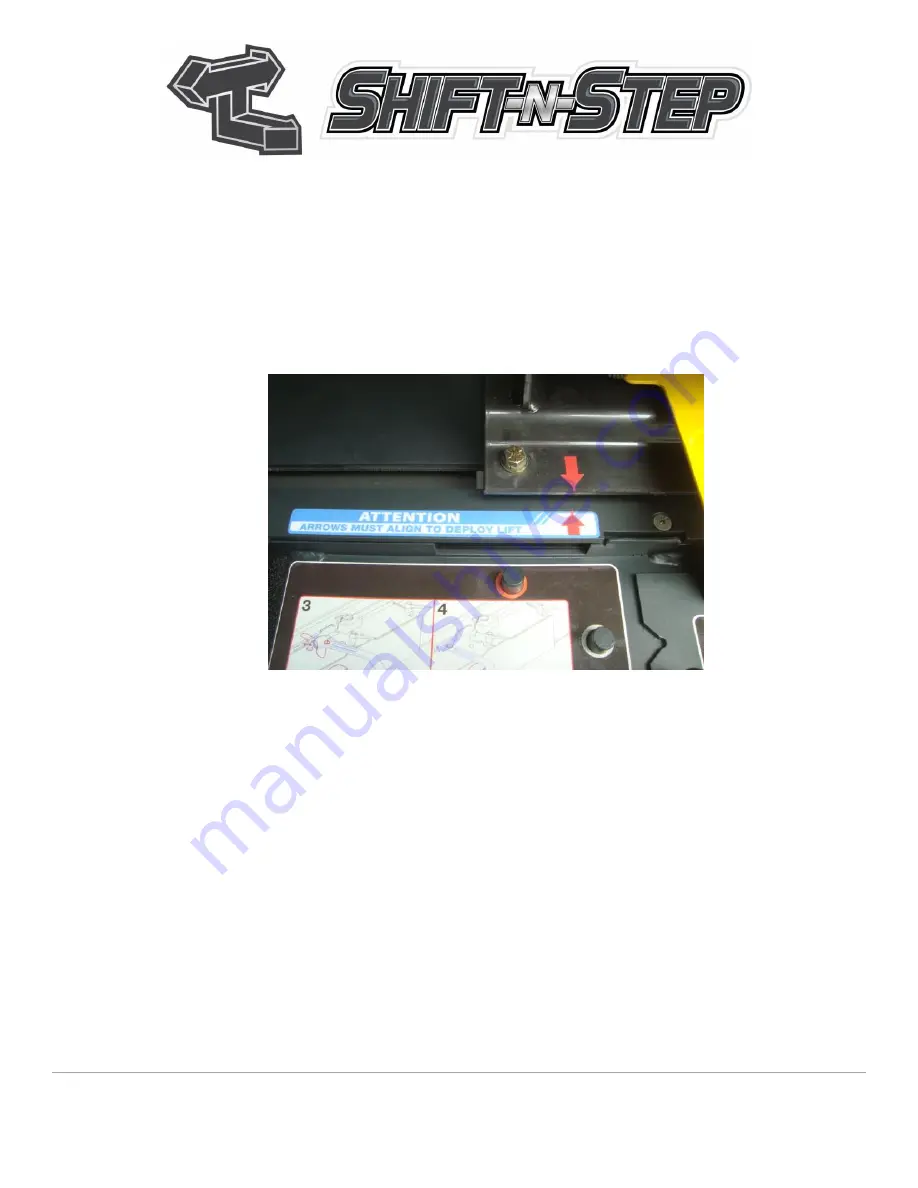
lift and the door or door opening causing damage to the vehicle and/or lift.  There is an arrow label on the left 

end of the lift base and a label stating “Arrows Must Align to Deploy Lift” 

nearer the left end of the Shift-N-Step 

base.  When these two arrows align, it indicates that the lift is shifted fully right and is safe to deploy. This is a 
visual guide only and it is not critical that the arrows be perfectly aligned but if there is a discrepancy of 

¼” 

or 

more in the arrow alignment (a

nd the “

Right 

Shift” pushbutton has been held until the unit stops on its own

), it 

may indicate an electrical or mechanical issue requiring attention and care should be taken that the lift will 
safely pass thru the door opening.    


 If the Shift-N-

Step does not move adequately to deploy the lift or if it makes “hard contact” at either end of its 

travel, the sensor(s) may require adjustment, repair or replacement. 

The Shift-N-Step may also be equipped with (optional) photoelectric sensors.  These sensors project an invisible 
beam across both the inboard and outboard sides of the ambulatory passenger pass through area.  If one of 

these beams is “broken” by a person’s leg, hand, or some other obstruction,

 the movement of the carriage will 

immediately stop regardless of button actuation.  The carriage will move again only when the obstruction is 
removed from the path of the beam and a button is being pressed. (

CAUTION

 - Operator override key switch 

disregards these sensors). 


Содержание Shift N Step

Страница 1: ...FENTON MOBILITY PRODUCTS 26 Center Street Randolph NY 14772 Shift N Step Operators Manual 1 OPERATORS MANUAL...

Страница 2: ...Shift N Step Operators Manual 2 Table of Contents 1 Basic System Description and Operation Page 3 2 Safety Page 4 3 Routine Maintenance Page 6 4 Normal Operation Pages 7 8 5 Electronic Operator Overr...

Страница 3: ...ft N Step system provide a complete package for the ultimate in safe convenient economical and easy transportation solutions for ambulatory as well as non ambulatory passengers These optional features...

Страница 4: ...ning labels in place and in good repair WARNING Never leave the Manual Override tool in position with the gear teeth engaged when using the push buttons Sudden and violent movement of the tool will oc...

Страница 5: ...in the arrow alignment and the Right Shift pushbutton has been held until the unit stops on its own it may indicate an electrical or mechanical issue requiring attention and care should be taken that...

Страница 6: ...ound moving parts or create a tripping slipping hazard and remove them Also be observant of any unusual movement sounds loose parts etc which may indicate a problem and bring them to the immediate att...

Страница 7: ...t Right button As long as the button is held in the carriage will continue to move until it is detected by a sensor at each end of the carriage travel at which point movement will stop NOTE Operator o...

Страница 8: ...inboard and outboard sides of the ambulatory passenger pass through area If one of these beams is broken by a person s leg hand or some other obstruction the movement of the carriage will immediately...

Страница 9: ...ation by use of the operator override key switch This switch bypasses most electronic devices and all safety switches and provides a direct power supply to the drive motor This mode is intended only a...

Страница 10: ...overload should occur release the key switch and allow several seconds for the overload to cool down and reset A mechanical malfunction which would prevent carriage movement may also cause this overlo...

Страница 11: ...movement of the tool will occur 1 The Drive Motor and gearbox unit are attached to the underside of a sliding mounting plate The output shaft of the gearbox is attached to a drive pinion gear The pini...

Страница 12: ...ing Handles are too tight to loosen by hand the Manual Override Tool is provided with a rectangular cutout which can be placed around the locking handle to aid in loosening DO NOT use the Manual Overr...

Страница 13: ...e the hole in the handle nearest the bird s beak over the pin nearest the notch in the edge of the motor plate Gray ring around hole to matching gray ring around pivot pin Engage the bird s beak into...

Страница 14: ...th the orange ring over the pin with the matching orange ring The Tool may be flipped over to provide the best angle for movement 4 With the gear teeth of the tool engaged into the gear teeth of the r...

Страница 15: ...til the pinion teeth can mesh properly with the gear rack teeth Insufficient engagement may result in gear slippage which will damage gear teeth while excessive pressure may result in binding and exce...

Отзывы: