background image

40

EN

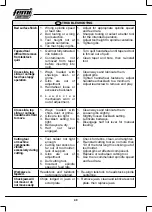
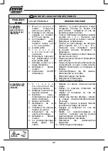
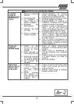
 TROUBLESHOOTING

Bad surface finish.

1.  Wrong  spindle  speed 

or feed rate.

2.  Dull  tooling  or  wrong 

tool selection.

3.  Tool  height  not  at 

spindle centerline.

4.  Too much play in gibs.

1.  Adjust  for  appropriate  spindle  speed 

and feed rate.

2.  Sharpen tooling or select a better tool 

for the intended operation.

3.  Adjust tool height to spindle centerline.

4.  Tighten gibs.

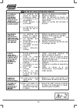
Tapered tool 

difficult to remove 

from tailstock 

quill.

1.  Quill not fully retracted 

into tailstock.

2.  Contaminants 

not 

removed  from  taper 

before  inserting  into 

quill.

1.  Turn quill handwheel until tapered tool 

is forced out of quill.

2.  Clean  taper  and  bore,  then  re-install 

tool.

Cross slide, top 

slide, or carriage 

feed has sloppy 

operation.

1.  Ways  loaded  with 

shavings,  dust,  or 

grime.

2.  Gibs  are  out  of 

adjustment.

3.  Handwheel  loose  or 

excessive backlash.

4.  L e a d s c r e w 

mechanism  worn  or 

out of adjustment.

1.  Clean ways and lubricate them.

2.  Adjust gibs.

3.  Tighten  handwheel  fasteners,  adjust 

handwheel backlash to a minimum.

4.  Adjust leadscrew to remove end play.

Cross slide, top 

slide, or carriage 

handwheel is hard 

to move.

1.  Ways  loaded  with 

chips, dust, or grime.

2.  Gibs are too tight.

3.  Backlash  setting  too 

tight.

4.  Bedways are dry.

5.  Half 

nut 

lever 

engaged.

1.  Clean ways and lubricate them.

2.  Loosen gibs slightly.

3.  Slightly loosen backlash setting.

4.  Lubricate bedways.

5.  Disengage  half  nut  lever  for  manual 

feeding.

Cutting tool 

or machine 

components 

vibrate 

excessively during 

cutting.

1.  Tool  holder  not  tight 

enough.

2.  Cutting tool sticks too 

far  out  of  tool  holder; 

lack of support.

3.  Gibs  are  out  of 

adjustment.

4.  Dull cutting tool.

5.  Incorrect 

spindle 

speed or feed rate.

1.  Check for debris, clean, and retighten.

2.  Re-install cutting tool so no more than 

1/3 of the total length is sticking out of 

tool holder.

3.  Adjust gibs at aff ected component.

4.  Replace or resharpen cutting tool.

5.  Use the recommended spindle speed 

and feed rate.

Workpiece is 

tapered.

Headstock  and  tailstock 

not properly aligned.

1. Re-align tailstock to headstock spindle 

centerline.

Chuck jaws will 

not move or do 

not move easily.

Chips  lodged  in  jaws  or 

scroll plate.

1.  Remove jaws, clean and lubricate scroll 

plate, then replace jaws.

Содержание JOB LINE DIGITO ML 350

Страница 1: ...www femi it IT TORNIO PER METALLO EN LATHE MACHINE FOR METAL FR TOUR POUR LE METAL DIGITO ML 350 8 35 61 20...

Страница 2: ...he original instructions please retain for future reference FR Traduction des instructions originales conserver pour tout usage futur IT MANUALE D USO EN USER MANUAL FR MANUEL D UTILISATION IT Per tut...

Страница 3: ...e GENERAL SAFETY REGULATIONS sheet FR Avant de proc der lire la notice NORMES G N RALES DE S CURIT IT Tensione Frequenza EN Voltage Frequency FR Tension Fr quence IT ACCENDERE la macchina EN SWITCH ON...

Страница 4: ...iduali EN Use personal protective equipment FR Utilisation de dispositifs de protection individuelle IT Matricola Anno di costruzione EN Serial number Year of manufacture FR Matricule Ann e de constru...

Страница 5: ...5...

Страница 6: ...N OFF D Luce accensione E Interruttore di arresto di emergenza F Mandrino a 3 gri e G Coperchio mandrino M Bancale N Volantino slitta porta utensili O Vaschetta olio P Leva chiocciola spaccata Q Volan...

Страница 7: ...ateur de direction arbre mandrin I Couvercle tourelle porte outil J cran de protection K Contre pointe L Corps contre pointe U Fusible V Manette de r glage vitesse W Couvercle terminal X Couvercle tro...

Страница 8: ...d Display Shows a digital readout of the spindle speed C Emergency Stop Button Pressed to cut power o Released to power on D Spindle Direction Switch Starts stops and reverses spindle E Power light Il...

Страница 9: ...ound Rest Handwheel Moves the tool toward and away from the workpiece at the preset angle of the compound rest J Half Nut Lever Engages disengages half nut for power feed and threading operations K Cr...

Страница 10: ...he quill position O Tailstock Lock Lever Secures tailstock in position along the bedway P Graduated Scale Indicates quill movement in increments of 0 025mm with one full revolution equaling 1mm of qui...

Страница 11: ...ile lathe is running or damage to machine may occur U Feed direction lever Used to select leadscrew rotation direction Up is for clock wise rotation and leftward carriage movement Center is neutral Do...

Страница 12: ...Jaw Chuck 1 B Chuck cover 1 C Tool post cover 1 D Oil tray 1 IT Fig 06 1 Ingranaggi Inventario L elenco delle parti spedite con il tornio riportato qui di seguito Prima di cominciarne l allestimento...

Страница 13: ...P Poign e volant chariot 1 Q Cl mandrin 3 gri es 1 EN Contents of the packaging Fig 8 H Hex Wrench Set 2 5 3 4 5 6mm 1 I Wrench Set 6 7 8 10 13 16mm 1 J Pot for Oil 1 K 3 Jaw Chuck External Jaw Set 1...

Страница 14: ...nut lever 2 Disengaged 3 Half nut lever 4 Engaged EN 1 Mounting Holes 2 Backplate Shoulder 3 Inside Taper EN 1 Spindle Backplate 2 Chuck Screw EN 1 Hex Nut 2 Lock Washer Fig 11 IT 1 Leva chiocciola sp...

Страница 15: ...5 Fourreau EN 1 Outside Set 2 Inside Set EN 1 Jaw Numbers 2 Jaw Guides EN 1 Lead Thread EN 1 Quill Lock Lever 2 Tailstock Lock Lever 3 O set Adjustment Screw 1 of 2 4 Quill Handwheel 5 Quill Fig 15 I...

Страница 16: ...ent EN 1 Carriage Handwheel 2 Compound Rest Handwheel 3 Slide handwheel EN 1 High Low range lever EN 1 Spindle Speed Display 2 Speed adjusting knob 3 Switch EN 1 Feed Direction Lever Fig 19 IT 1 Volan...

Страница 17: ...t te creuse 3 crouhexagonal 4 Engrenage D EN 1 Half nut lever EN 2 A Gear 20T 3 C Gear 20T 4 D Gear 80T 5 B Gear 80T EN 1 B C Gear 2 Cap Screws 3 Hex Nut 4 D Gear Fig 23 IT 1 Leva chiocciola spaccata...

Страница 18: ...e B C 2 Vis t te creuse 3 Engrenage D 4 crou hexagonal FR 1 Vis t te creuse externes 2 Vis t te creuse internes EN 1 A Gear 2 B Gear 3 C Gear 4 D Gear 5 Adjuster Hex Nut EN 1 B C Gear 2 Cap Screws 3 D...

Страница 19: ...s grain EN 1 Leadscrew 2 End Bracket 3 Retaining Nut 4 Set Screw EN 1 Cross Slide Adjustment Fasteners EN 1 Top Slide Adjustment Fasteners EN 1 Gib 2 Half nut 3 Set Screw Fig 31 IT 1 Madre vite 2 Sta...

Страница 20: ...1 Balai FR 1 Capuchon balai 2 Balai EN 1 Fuse Holder 2 Fuse 3 Fuse Holder Hole EN 1 Screws 2 Brush Cap EN 1 Brush EN 1 Brush Cap 2 Brush Fig 35 IT 1 Porta fusibile 2 Fusibile 3 Foro porta fusibile Fi...

Страница 21: ...FR 1 Courroie de calageRoue capteur EN 1 Side Cover 2 Outer Spanner Nut 3 Sensor Wheel 4 Speed Sensor EN 1 Motor Mount Hex Nuts EN 1 Timing beltSensor Wheel Fig 39 IT 1 Coperchio laterale 2 Ghiera a s...

Страница 22: ...22 325 mm 760 mm 315 mm 2 1 20 Kg 3...

Страница 23: ...in ambienti umidi o bagnati n esporlo alla pioggia Mantenere ben illuminata l area di lavoro 13 Tenere bambini e visitatori a debita distanza Tutti i visitatori devono essere tenuti a distanza di sic...

Страница 24: ...longitudinali 0 1mm r Slitta porta utensili Slitta trasversale e Carrello Torretta porta utensile 4 vie Corsa slitta porta utensili 65mm Corsa slitta trasversale 65mm Corsa carrello 370mm Corpo contr...

Страница 25: ...l rodaggio albero mandrino 1 In modo positivo completare il collaudo 2 Impostare l interruttore direzione albero mandrino su F avanzamento assicurarsi che la leva di gamma su BASSO e far funzionare il...

Страница 26: ...tto dell ingranaggio a spirale nel corso della prima rotazione Corpo Contropunta Fig 18 Il corpo contropunta tipicamente utilizzata per supportare pezzi in lavorazione lunghi sul lato opposto del mand...

Страница 27: ...llineano la leva si sposter agevolmente in sede 2 Ruotare l indicatore velocit variabile su 0 3 Ruotare l Interruttore direzione albero mandrino su F e premere il pulsante ON 4 Regolare la velocit no...

Страница 28: ...mento libero che si avverte mentre si inverte il senso di rotazione mediante il volantino E possibile e ettuare la regolazione sulla madre vite della slitta trasversale Prima di iniziare qualsiasi reg...

Страница 29: ...bile integrato progettato per bruciarsi per proteggere parti elettriche delicate in caso di eventi termici estremi o di sovraccarichi Se l albero del mandrino non si avvia sostituire il fusibile Sosti...

Страница 30: ...corretta tensione di alimentazione 6 Assicurarsi che il circuito sia correttamente dimensionato ed esente da cortocircuiti Ripristinare l interruttore o sostituire fusibile 7 Controllare Riparare li r...

Страница 31: ...avanzamento e giri min di taglio 6 Assicurare o centrare adeguatamente il pezzo in lavorazione sul mandrino o la piastra frontale sostituire un mandrino difettoso Scadente nitura super ciale 1 Veloci...

Страница 32: ...a della chiocciola spaccata per una tornitura manuale L utensile di taglio o i componenti macchina vibrano eccessivamente durante le operazioni di tornitura 1 Porta utensile non serrato su cientemente...

Страница 33: ...ns or expose them to rain Keep work area well lighted 13 Keep children and visitors away All visitors should be kept a safe distance from the work area 14 Make the workshop child proof Use padlocks ma...

Страница 34: ...eads Range of Longitudinal Feeds 0 1mm r Top Slide Cross Slide Carriage Tool Post 4 Way Top Slide Travel 65mm Cross Slide Travel 65mm Carriage Travel 370mm Tailstock Quill Travel 50mm Quill Taper MT2...

Страница 35: ...lever to HIGH then operate lathe at 2000 RPM for 10 minutes then stop spindle 5 Run lathe in reverse at 2000 RPM for 10 minutes then turn speed dial to 0 turn spindle direction switch to 0 and press E...

Страница 36: ...ce the tool moves Compound Rest Handwheel Use this handwheel to move the cutting tool lin early along the set angle of the compound rest Set the compound rest angle by hand rotating it and securing in...

Страница 37: ...r threading 2mm 1 Disconnect Machine from power 2 Located 2mm thread on gear chart show Fig 27 3 Remove end cover 4 Loosen hex nut behind B C change gear shaft then slide B C gear away from D gear Fig...

Страница 38: ...ad screw while opening and closing Repeat step 3 4 if necessary until satis ed with feel of half nut engagement Fuse Replacement This lathe features an on board fuse designed to blow to protect sensit...

Страница 39: ...ting speed too fast 2 Wrong workpiece material 3 Machine undersized for task 4 Motor overheated 5 Computer board at fault 6 Motor speed dial at fault 7 Timing belt slipping 8 Motor brushes at fault 9...

Страница 40: ...um 4 Adjust leadscrew to remove end play Cross slide top slide or carriage handwheel is hard to move 1 Ways loaded with chips dust or grime 2 Gibs are too tight 3 Backlash setting too tight 4 Bedways...

Страница 41: ...n clair e 13 Maintenir les enfants et les visiteurs loign s de la machine Tous les visiteurs doivent tre maintenus distance de s curit de la zone de travail 14 Rendre le laboratoire une zone de s curi...

Страница 42: ...x 0 1mm r Coulisseau porte outils Coulisseau transversal et Chariot Tourelle porte outil 4 voies Course coulisseau porte outils 65mm Course coulisseau transversal 65mm Course chariot 370mm Corps contr...

Страница 43: ...t s assurer que le levier de la gamme de vitesse est sur PETITE et faire fonctionner le tour pendant 10 minutes 100 tours min 3 Faire fonctionner le tour 1000 tours min pendant 10 minutes ensuite tour...

Страница 44: ...ihoraire a n de bloquer le corps contre pointe sur les guides du banc Usage du fourreau 1 Desserrer le levier de blocage du fourreau 2 Tourner le volant du fourreau en sens horaire a n d approcher le...

Страница 45: ...la photo ci dessous pour identifier les engrenages de remplacement A B C et D auxquels fait r f rence aussi le sch ma des engrenages de motorisation de la t te porte mandrin Les sous sections suivante...

Страница 46: ...e creuse par incr ments petits et uniformes v ri er ensuite le mouvement du coulisseau en tournant le volant Remarque Tourner les vis t te creuse en sens horaire pour serrer les clavettes et les tourn...

Страница 47: ...5 Desserrer les crous hexagonaux de xation du moteur Fig 40 6 D chausser la courroie de calage et en installer une nouvelle en s assurant que les dents de la courroie s ins rent correctement dans les...

Страница 48: ...S assurer que la tension d alimentation soit correcte 6 S assurerquelecircuitestdimensionn correctement et sans courts circuits R tablir l interrupteur ou remplacer le fusible 7 Contr ler R parer les...

Страница 49: ...le r gime tours min de coupe corrects 6 Fixer ou centrer convenablement la pi ce usiner sur le mandrin ou sur la plaque frontale remplacer l ventuel mandrin d fectueux Finissage de surface de mauvais...

Страница 50: ...ides du banc 5 D brayer le levier du demi crou pour un tournage manuel L outil de coupe ou les composant de la machine vibrent excessivement pendant les op rations de tournage 1 Serrage insu sant du p...

Страница 51: ...51...

Страница 52: ...TCH DIRECTION SWITCH POWER LAMP 10 7 1 5 9 2 6 3 8 4 12 11 11 12 P1 P3 P2 A L2 A L1 4 3 2 1 3 2 1 24 24 24 23 13 14 14 14 14 P1 P1 P2 P2 P3 P3 12 12 11 11 7 7 9 9 5 5 10 10 10 6 L2 L2 2 A 12 12 L1 L1...

Страница 53: ...35 36 8356120 36 37 8356120 37 38 8356120 38 39 8356120 39 40 8356120 40 41 8356120 41 42 8356120 42 43 8356120 43 44 8356120 44 45 8356120 45 46 8356120 46 47 8356120 47 48 8356120 48 P C N 49 835612...

Страница 54: ...56120 138 139 8356120 139 140 8356120 140 141 8356120 141 142 8356120 142 143 8356120 143 144 8356120 144 145 8356120 145 146 8356120 146 147 8356120 147 148 8356120 148 149 8356120 149 P C N 150 8356...

Страница 55: ...55...

Страница 56: ...CR GCA USA 120 60 MA VN 127 50 KSA EC MEX 127 60 RL 200 50 AL ANG RA BY K RCH RC UAE HK MA RUS SRB ZA T ROU VN KZ LV LT L 220 50 KSA BR ROK RP PE 220 60 DZ A B BG CI HR DK EST FIN F D HKJ GR IND RI UK...

Страница 57: ...more it conforms to the following regulations and relative implementation 2014 30 UE 2014 35 UE 2011 65 UE 2012 19 UE D CLARATION DE CONFORMIT selon la Directive Europ enne 2006 42 CE Annexe II A FEMI...

Страница 58: ...58 Ingombro per etichetta FAC SIMILE Ingombro per etichetta FAC SIMILE...

Страница 59: ...______________________ ____________________________________________________________________________________________ ____________________________________________________________________________________...

Страница 60: ...Via Del Lavoro 4 40023 CASTEL GUELFO BO Italy Tel 39 0542 487611 Fax 39 0542 488226 E mail infocom femi it www femi it 6 90 21 51 Rev 0 2020 12 17...

Отзывы: