11
I V . E X T E R N A L I N T E R F A C E
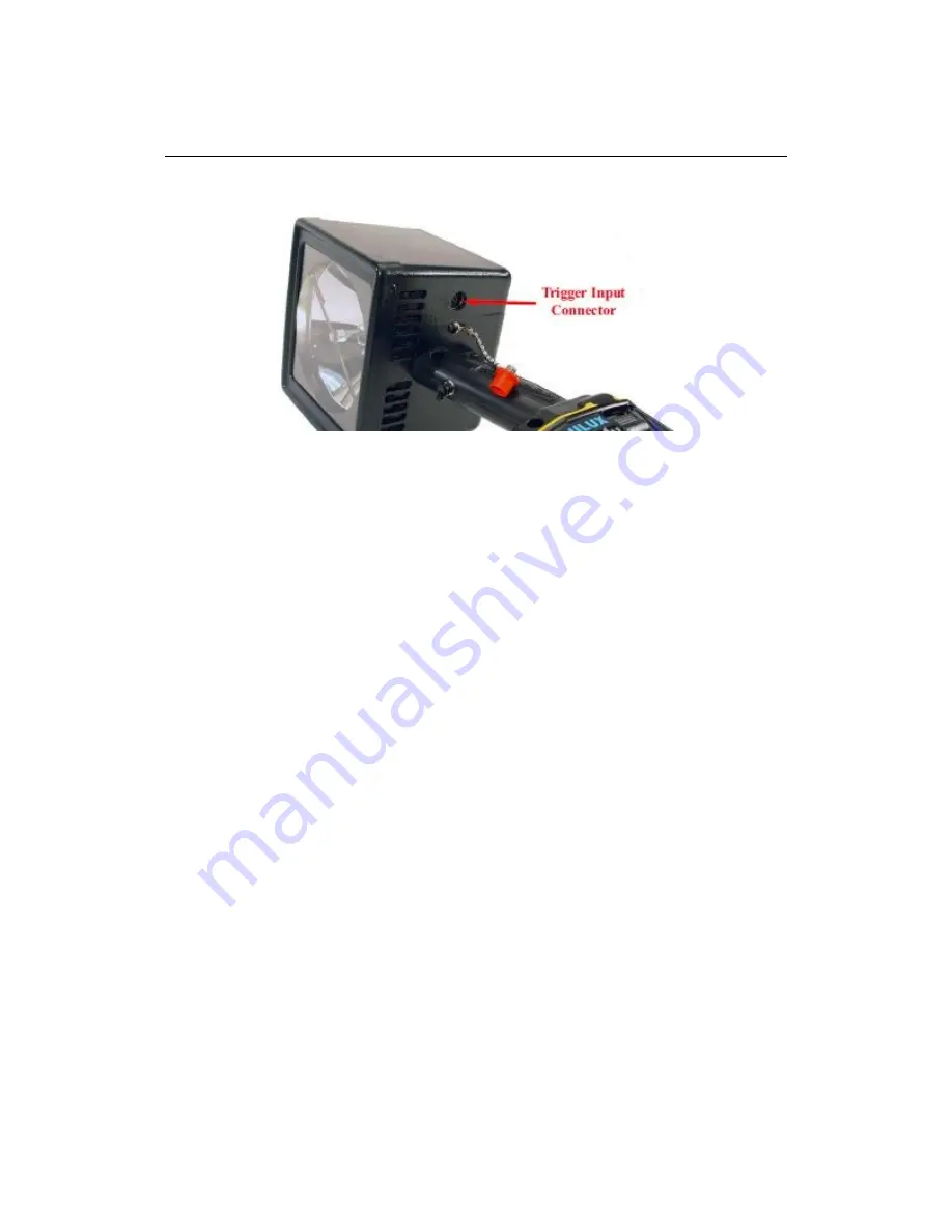
The trigger input connector is located on the unders ide of the PowerStrobe.
Trigger Input Connector Pin Assignments
The trigger connector i s a six pin circularDin type.
The connector pin assignments & descriptions are as follows.
• Pin 1 : Open collector trigger output for synchronizing a second unit
• Pin 2 : Video signal trigger input
• Pin 3 : Contact Closure or Pulse Trigger input,
depending on the customer option ordered
• Pin 4 : External Mode control line for selecting external trigger mode
(See Note below)
• Pin 5 : Trigger Supply +14V DC output, connected to a DC Power Pack
• PIN 6 : Ground reference for all trigger signals and trigger DC supply
Note:
The trigger connector mating plug used on the PowerStrobe external trigger
cables supplied by Feltest contains an internal jumper from Pin 4 to Pin 6.
This internal connection automatically selects external mode of operation
Содержание PowerStrobe
Страница 1: ...1 Manual PowerStrobe Release Date 01 2011...


