background image


I. WELCOME TO THE POWERSTROBE 


FEATURES 

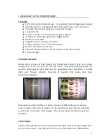
Self-contained portable design - no separate high voltage power supply 
Operates from a rechargeable 14V DC Power Pack or A/C connector  
Provides three Intensity Levels in low flash ranges 
Long lamp life 
Accepts remote synchronization (trigger) signals  
Variable 0- 360 degree External Trigger Delay 
Measures True RPM 
Rugged  Lamp  mounting  assembly 
A large,  bright  easy  to  read  LED  display 
Built  in  low  battery  indicator 
Superior  design  reflector  offers  uniform  area  illumination 
1  hour  charger 


STOPPING THE BLUR


When  objects  move  at  high  speed,  the  human  eye  cannot  focus  on  a  single 
image. As  a  result,  the  eye  can  only  see  "blur".   But  strobe  lighting stops  the 
blur.  By  flashing  with  high  intensity  for  extremely  short  durations,  a  strobe 
light  will  "freeze"  objects  traveling  at  speeds  that  cause  blur.  [

See 

Illustrations  Below


During  these  short  flashes,  an  object  moving  at  600  meters  per  minute 
moves  only  0.2mm  a n d   it  appears  to  be  stationary  since  the  eye  captures 
and  retains  only  brief  visual  images.   This  result  makes  detailed inspection 
possible.    


TRUE COLORS


Feltest  PowerStrobes  emit  an  excellent  white  light  approaching sunlight  that 
reveals  true  colors.   The  light's  scientific  color  temperature  is  6500  Kelvin. 


Содержание PowerStrobe

Страница 1: ...1 Manual PowerStrobe Release Date 01 2011...

Страница 2: ...p used in this unit Do Not Operate a PowerStrobe in Explosive Areas CAUTION Lens may be extremely HOT after operation allow to cool as necessary Servicing Servicing this equipment beyond changing the...

Страница 3: ...rnal Mode PowerStrobe Control Panel Intensity Flash Rate Range Control Auto Scale Flash Rate Range IV 11 EXTERNAL INTERFACE Trigger Input Connector Pin Assignments V 12 SPECIFICATIONS Photometry Diagr...

Страница 4: ...ger STOPPING THE BLUR When objects move at high speed the human eye cannot focus on a single image As a result the eye can only see blur But strobe lighting stops the blur By flashing with high intens...

Страница 5: ...cted in the immediate area See Warning on first page Therefore 50 F S should be your minimum flash rate Flash rates should not allow more than 15cm to 30cm of material to pass between flashes Therefor...

Страница 6: ...es V C Option Video Contact Closure Video 1v p p unterminated triggers on 50Hz or 60Hz vertical sync Contact Contact closure or open collector 8VDC 10mA rating V P Option Video Pulse Video 1v p p unte...

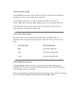
Страница 7: ...Flash Rate Ranges Maximum flash rates of 6000 F M 12000 F M and 18000 F M are provided and are automatically set by the selected intensity level as fol lows Intensity Level Flash Rate Range 100 30 F M...

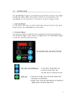
Страница 8: ...control panel 2 External Mode The external mode of operation is automatically selected whenever the prewired trigger signal cable is plugged into the PowerStrobe trigger connector See interface secti...

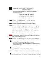
Страница 9: ...to the PowerStrobe trigger input connector When operating in Phase Delay mode the flash rate display shows the phase delay from 0 to 360 set by the Up Down rate keys Five Digit Display for indicating...

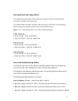
Страница 10: ...oules flash Max Flash Rate 300 F S 18000 F M Auto Scale Flash Rate Range Feature The PowerStrobe has a built in flash rate divider multiplier feature for maintaining synchronous flash rates throughout...

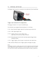
Страница 11: ...gger input Pin 3 Contact Closure or Pulse Trigger input depending on the customer option ordered Pin 4 External Mode control line for selecting external trigger mode See Note below Pin 5 Trigger Suppl...

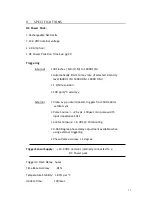
Страница 12: ...tion 100 ppm C accuracy External Video 1vp p unterminated triggers from 50Hz 60Hz vertical sync Pulse Source 2 5v pk 100 sec min pulse width Input impedance 10k Contact Closure 8 VDC 10mA rating 0 360...

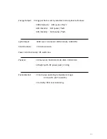
Страница 13: ...33 Intensity 0 28 joules flash Light Output 1800 Lux at 4 6 meter 100 intensity 6000 F M Flash Duration 20 microseconds Power into Flash Lamp 85 watts max Physical Dimensions 168 3mm X 161 9mm X 336...

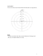
Страница 14: ...ation pattern at a target distance Inches Centimeters Lux 24 in 60 cm 200 18 in 45 cm 300 12 in 30 cm 500 6 in 15 cm 1000 2 in 5 cm 1800 NOTES The distance increments shown above represent displacemen...

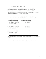
Страница 15: ...r demand The table below illustrates a few examples of the DC Power Pack run time as a function of operating flash rate intensity Operating Conditions DC Power Pack Run Time Flash Rate 3600 F M 80 min...

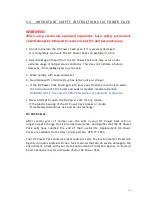
Страница 16: ...or a minimum of 10 minutes and seek immediate medical attention MEDICAL NOTE The liquid is 25 35 solution of potassium hydroxide Never attempt to open the DC Power Pack for any reason If the plastic h...

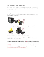
Страница 17: ...ger to an appropriate outlet before inserting DC Power Pack 3 Insert the DC Power Pack into the charger as shown above The red light will blink continuously indicating that the charging process has st...

Страница 18: ...nt pack to determine if charger is OK If the new pack charges correctly then the original pack is defective and should be returned to Feltest for recycling If the new DC Power Pack elicits the same tr...

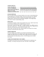
Страница 19: ...ure You may also charge a partially used pack whenever you desire with no adverse effect on the DC Power Pack 5 Under certain conditions with the charger plugged in to the power supply the exposed cha...

Страница 20: ...the DC Power Pack after use avoid placing the charger or DC Power Pack in a warm environment such as in a metal shed or an uninsulated trailer CAUTION To reduce risk of injury charge only Feltest rec...

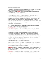
Страница 21: ...recommended if the actual inspection application requires peak lamp performance WARNING PROCEED WITH CAUTION The PowerStrobe lamp operates at LETHAL High Voltages The lamp and lens may be extremely H...

Страница 22: ...22 3 Remove the 2 screws from the Strap Anode Socket board Step 3 4 Remove Flash Lamp from the lamp sockets Anode Cathode and install new lamp by reversing the steps of these instructions Step 4...

Страница 23: ...p reflector from the mounting Support Step 2 3 Lift out the reflector to expose the Intake Air Duct filter Assy and Air Exhaust filter For changing Exhaust filter follow the steps 4 1 and 5 1 after st...

Страница 24: ...ith the Air Duct Filter Assy Step 5 Note 1 6 Remove 4 screws holding the Air Duct Filter assembly and replace with new Air Duct filter Assembly by reversing the steps of these instructions NOTE 1 Be s...

Страница 25: ...mounted on the casing See fig below can be removed by loosening two 2 screws that secure the filter holder thru the outer air exhaust slots 5 1 Remove the filter holder and filter and install new Exha...

Страница 26: ...TRALIA 56 1040 220UK 1 HOUR CHARGER 220V UK 62 1230 WINDOW TRIM RING 63 1039 FRONT BEZEL 77 1055 14 4V DC POWER PACK 81 1980 SIDE DEFLECTOR INTAKE AIR 81 1981 BOTTOM DEFLECTOR EXHAUST AIR 85 1166 LAMP...

Страница 27: ...45 1047 Window Trim Ring UPN 62 1230 Lens UPN 88 1147 Front Bezel UPN 63 1039 Power Board PCB Assy UPN 05 1594 Control PCB Assy UPN 05 1412 1 External Trigger PCB Assy UPN 05 1421 Air Duct Filter Ass...

Страница 28: ...28 Air Exhaust Filter UPN 54 1158 Head Assembly Complete UPN 04 1581 1 Hour Charger 110V or 220V UPN 56 1040 110 UPN 56 1040 220 14 4 DC Power Pack DC Power Handle UPN 77 105 UPN 04 1583...

Отзывы: