You will need two boards approximately the same size, both approx. 2” x 4” and at
least 2ft long. If the boards do not have planed faces, then join one side of each
board first.
Make sure that the feed rollers are engaged and there is suitable extraction. With the
joined surface always facing the cast iron table, plane the two workpieces, one at
either side of the table (as shown in the tolerancing information). Keep passing the
workpieces through until the top surface is completely planed. Always pass the same
workpiece through on the same side of the table. Be sure sure to lock the table in
position each time after raising or lowering it.
When the workpieces have been planed, using a pair of vernier calipers, measure the
thickness of both workpieces. Check that the two measurements are the same within
tolerance.
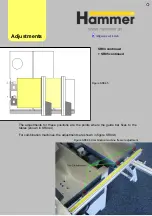
If
the
measurements
indicate that the
planer is out of
tolerance, then an
adjustment
is
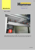
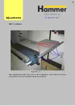
necessary. Figure
PL01.1 shows 3 of
the 4 adjustment
positions fo
table. To move
one side of the
table up or down,
make
an
adjustment at both
of the screws on
that side by an
equal amount.
r the
PL01.1
fter adjusting, perform the test again and re-adjust as necessary.
A
Adjust
ments
PL01 Planer Test
N.B. Always raise the table to the desired final position and lock it in place
Содержание Hammer
Страница 1: ...Machine Setup Guide InstallVersion1 09...
Страница 5: ...15 Completion You re Good To Go 16 FAQ s 17 Links Contact Details Contents 3...
Страница 32: ...The rip fence side is complete 11 Assembly...
Страница 60: ...Test Point Unit type Tolerance Target No snipe Metric Imperial Alignments Adjustme nt Link JR07 Snipe Check...
Страница 74: ...Figure SS03 2 End position 2 Adjustments Alignme nt Link SS03 continued...
Страница 79: ...Figure SS07 3 Crosscut stop and block adjustment Adjustments Alignme nt Link SS07 continued...

