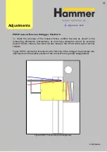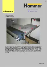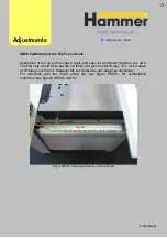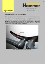
Figure SR04.4 Rip fence bar securing points
So far the freecut has only been checked across the rip fence bar per the width of the
cast iron table. The next step is to check the free cut across the extension tables.
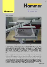
Figure SR04.5 illustrates the two positions you would need to check and also shows
how with two boards (both rip-cut off the rip fence) the check can be made in the
same way as before. This clearly requires that both of the boards have near-perfect
parallel edges, so they must be ripped with great care in order for this check to be
accurate.
Adjust
ments
Continued…
SR04
continued
+
SR0
5
continued
Содержание Hammer
Страница 1: ...Machine Setup Guide InstallVersion1 09...
Страница 5: ...15 Completion You re Good To Go 16 FAQ s 17 Links Contact Details Contents 3...
Страница 32: ...The rip fence side is complete 11 Assembly...
Страница 60: ...Test Point Unit type Tolerance Target No snipe Metric Imperial Alignments Adjustme nt Link JR07 Snipe Check...
Страница 74: ...Figure SS03 2 End position 2 Adjustments Alignme nt Link SS03 continued...
Страница 79: ...Figure SS07 3 Crosscut stop and block adjustment Adjustments Alignme nt Link SS07 continued...

