background image

Guilin Feiyu Electronic Technology Co., Ltd


Guilin Feiyu Electronic Technology Co., Ltd            http://www.feiyudz.cn            E-mail: [email protected]              Page 2


Auto Return To Launch Mode(RTH) 

The  GPS  Module  must  be  connected  to  the  DoS  with  at  least  5  GPS  satellites 

detected.In this Mode, pitch, roll, yaw and altitude control method is the same as Hovering 
Mode.  Pitch,  roll  sticks  released  will  automatically  fly  the  aircraft  back  to  the  take-off 
point,


Maximum return to home point speed:


5.5m/s. 


Camera Gimbal Stabilization 

DoS  multi-rotor  firmware,when  is  used  to  control  the  aircraft  under  6  axis,  can 

simultaneously control two axis Camera Gimbal Stabilization 


DoS can connect with the Hornet-OSD and the Data Radio 

DoS has one UART interface for connecting the FY-data radio and the OSD module. 

It can realize the following function by combing them. 

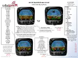
First  Person  View  (FPV):

  Can  be  connected  to  the  Hornet  -  OSD,  the  flight  data 

overlay to video output,and through the vodeo transmission  system to send back, let you 
enjoy the fun of FPV. And it will be easier to operate FPV with the functions of automatic 
balance, Hovering and Auto Return To Launch.   

Real  time  telemetry-real  time  monitor:

  Real  time  telemetry-real  time  monitor  the 

flying state, using the Data Radio to lengthen the remote control distance. 

For more information, please refer to the FY-OSD and FY Data Radio manual. 

1.


DoS standard configuration


Standard configuration 

●DoS control module *1; 

●RC receiver connecting wires * 1; 

●USB cable *1; 

●Velcro double sided tape * 2; 
 

Optional accessory 

●DoS vibration absorbing mount *1; 

●GPS module *1; 

●Hornet OSD module;   

●Data Radio; 

●Remote Adaptor; 

2.


Technical Specification: 


DoS module 

Input voltage   


: 4.0 ~ 6.0 Volt; 

Current 


: 50mA (5V); 

Size     


: 47 x 30 x 11 mm; 

Weight (excluding wires)  

: 25g; 

Temperature range 


: -25 ° C ~ +70 ° C; 

Control frequency  


:400HZ ;                           

Maximum rate of rotation  

: ≤ 2000 °/s. 


Содержание DoS

Страница 1: ...rately measure flight attitude the earth azimuth and through the barometer to measure relative altitude This manual mainly introduces DoS firmware for Multi rotor flight system The firmware for Multi rotor flight system above V2 10 can realize the following functions We will continue updating new firmware to improve performance and update functions please pay attention to the latest news FeiYu off...

Страница 2: ...unction by combing them First Person View FPV Can be connected to the Hornet OSD the flight data overlay to video output and through the vodeo transmission system to send back let you enjoy the fun of FPV And it will be easier to operate FPV with the functions of automatic balance Hovering and Auto Return To Launch Real time telemetry real time monitor Real time telemetry real time monitor the fly...

Страница 3: ...PS and UART interface GPS module interface The GPS pin interface consist of GND 5V RX0 The characteristics are Baud rate 38400 Data bits 8 Stop Bits 1 Parity None Interface Features TTL level No 1 2 3 4 RC receiver interface SW1 RUD Servo THR Servo ELE Servo GND Power 5V AIL Servo SW2 position 1 2 3 servo signal output 900 1200US 1200 1800US 1800 2100US function stabilized mode Hovering Mode Auto ...

Страница 4: ...s as follows Physical connection diagram Put the 4P Y line inserted into DoS s GPS port Data Radio interface The UART pin interfaces consist of GND power 5V TX1 RX1 The characteristics as follows Baud Rate 19200 Data bits 8 Stop Bits 1 Parity None Interface Features TTL level This pin interfaces connects to the Data Radio PC computer serial port or OSD module You can set DoS control parameters and...

Страница 5: ...rvos for a long time will cause the Camera Gimbal servos overheat 2 If you use DoS to control Octocopter aircraft S7 and S8 ports will not output Camera Gimbal control signal any more 5 Power Supply DoS input voltage is 4 0 6 0 V you can use a stabilized voltage supply or directly use ESC s 5 V power supply most of the ESC power supply can meet the requirements DoS and the RC receiver use the same...

Страница 6: ... unable to keep the flight altitude and position You can use your own DIY shock absorbing devices to do the shock absorbing but we recommend using suspending damping installation especially use DoS vibration absorbing mount which product by FeiYu Tech it can meet the requirements of most of the conditions and in addition you need to try to reduce the vibration of the motors and oars Installtion po...

Страница 7: ... recommed using suspending damping installation especially use DoS vibration absorbing mount which product by FeiYu Tech You can find purchase method from FeiYu official website www feiyudz cn Installation process as follows You need a allen driver 1 Use screws to install the four support columns on the baseboard 2 Stick the solid foam pads dampers to the cover board four interior Angle position ...

Страница 8: ... improve the damping effect you can stick copper sheet or other sheet metal which cannot be magnetized on the bottom of the DOS Otherwise the magnetized sheet metal will disturb the internal magnetic field sensors 4 Use screws to fix the cover board to the four support columns 5 Stick the circular ring foam pads dampers to the four rounded corners on the baseboard vibration absorbing mount Then fi...

Страница 9: ...els are required to control the DoS Flight Modes a 3 position switch SW1 d the other 3 position switch SW2 is not used in firmware V2 0 so you do not need to connect Wire color Receive channel White bundled with red black aileron Channel 1 orange elevator Channel 2 green throttle Channel 3 yellow rudder Channel 4 brown SW 1 Any free channel controlled by A 3 way switch or dial knob Channel 5 blue ...

Страница 10: ... DoS remains stationary that means you need to do the Gyro reset The Gyro reset must be done before the Combination Stick Commands after execute Combination Stick Commands you can not do the Gyro reset Initialization Reset Process 1 Power on DOS and keep stationary 2 Switch to stabilized mode 3 On SW1 switch stabilized mode to hovering mode 6 times time interval has to be less than 3 seconds as fo...

Страница 11: ...t satisfies the requirement of flight but after that you can wait over 30 seconds to let the GPS positioning is more stable and accurate 12 Other considerations 1 Please as far as possible to maintain the current altitude when switch Attitude Stabilized Mode to Hovering Mode In Hovering Mode DoS can automatic control flight altitude Climbing and descending rate is directly related to the throttle ...

Страница 12: ...om Page 12 sticks the aircraft will hover to a new position 13 DoS Setting Software and installation and debugging instructions connection mode First need install USB TTL device driver you can download it form our website www feiyudz cn Software Interface Description Parameter in the following picture is default parameter USB Cable ...

Страница 13: ...setting software otherwise will cause the aircraft abnormal condition Motor Mixer The following pictures display the rotation direction and serial number of each motor each ESC should be connected to the DoS S1 S8 interface Pay attention that once you choosed the control type the corresponding position motor rotate direction have to be completely the same as the picture If the motor rotate directi...

Страница 14: ...command stick the bigger the value the quicker the reaction Increase it for sharper and quicker leveling action after command stick released Unstable shaking flying and the control feeling will be stiffness and rigid if the value is too high and sluggish leveling action and slow braking if too small Control Gain Control gain use for stabilizing the flight attitude To the gains of Pitch and Roll if...

Страница 15: ...nough 1 The multi rotor can lock the altitude when the throttle stick is at center position 2 The change of altitude is small during the flight along a route You can increase the gain slowly 10 each time until the vibration emerges along the vertical direction or the reaction of throttle stick is too sensitive then decrease 20 of the gain Now it is a suitable Vertical gain Control I This value gen...

Страница 16: ...situation disappear If the camera gimbal go back to Neutral is too soft As a result you should slowly increase 10 20 each time corresponding direction Gimbal Gain 3 Gimbal Neutral The default Gimbal Neutral is 1520 Power on and put the camera gimbal into level position observe the servos position If the servos is not in the Neutral value please through adjust the to corresponding servos Gimbal Neu...

Отзывы: