APPLICATION NOTE
final
public (B)
2007-03-01
N70100-0de-ID-B.doc
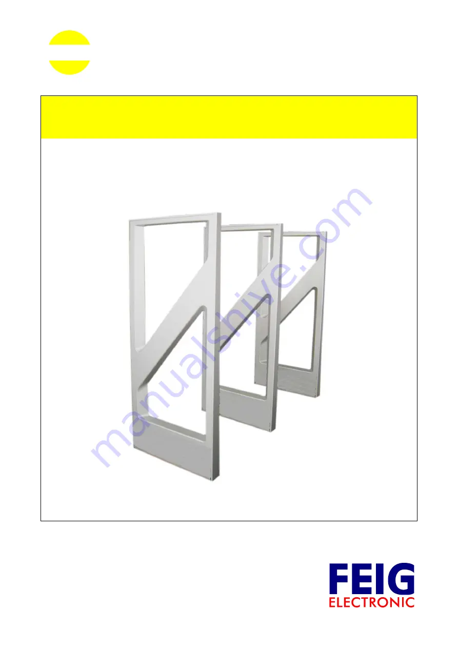
OBID i-scan
®
ID ISC.ANT1400/760
Antennen Aufbau mit 3-5 Antennen
Multiple-Gate setup with 3-5 Antennas
(deutsch / english)
Страница 1: ...APPLICATION NOTE final public B 2007 03 01 N70100 0de ID B doc OBID i scan ID ISC ANT1400 760 Antennen Aufbau mit 3 5 Antennen Multiple Gate setup with 3 5 Antennas deutsch english ...
Страница 2: ...OBID i scan Application Note ID ISC ANT1400 760 C B FEIG ELECTRONIC GmbH Seite 2 von 31 N70100 0de ID B doc D E U T S C H deutsche Version ab Seite 3 english version from page 18 E N G L I S H ...
Страница 3: ...nkbar Die in diesem Dokument gemachten Installationsempfehlungen gehen von günstigsten Rahmenbedingun gen aus FEIG ELECTRONIC GmbH übernimmt weder Gewähr für die einwandfreie Funktion in system fremden Umgebungen noch für die Funktion eines Gesamtsystems welches die in diesem Dokument be schriebenen Geräte enthält FEIG ELECTRONIC weist ausdrücklich darauf hin dass die in diesem Dokument beschriebe...
Страница 4: ...bis 5 Antennen 6 2 1 Anordnung der Antennen 6 2 2 Antennenabstand und Erfassungsgeschwindigkeit 7 2 3 Aufbau und Einstellen mit den Antennen Typ C und B 8 2 3 1 Benötigte Komponenten 8 2 3 2 Aufbau des Personengates Antenne Typ C und B 9 2 3 3 Einstellung des Multiplexer 10 2 3 4 Konfiguration des Readers 12 2 3 5 Abgleichen des Personengates 14 Readereinstellung für Signalgeber 15 2 4 Aktivieren ...
Страница 5: ...ionszeiten und geringeren Lesereichweiten Hinweise Bitte lesen Sie vor der Montage der Antennen die 4 1 Projektierungshinweise in der Mon tageanleitung M50700 4d ID B doc Der Abstand der Antennen eines Gates ist abhängig von der Antennenkonfiguration Werden mehrere Antennen oder Gates mit verschiedenen Readern verbunden ist ein Min destabstand von 8 m zwischen den Antennen oder Gates einzuhalten B...
Страница 6: ...ng der Antennen Die Antennen sind wie folgt anzuordnen Die Antenne Typ C sollte immer in der Mitte des Gates angebracht werden um ein verlängern der Koaxialkabel zu vermeiden Ab 3 Antennen vom Typ B lässt sich dies nicht mehr vermeiden Folgende schematischen Darstellungen zeigen den Aufbau der verschiedenen Varianten Der Anschluss der Antennen an den Multiplexer ist in Tabelle 1 Anschluss der Ante...
Страница 7: ...rfassungsgeschwindigkeit Die Durchgangsbreite der Gates siehe Montageanleitung Kapitel Projekthinweise darf eine Breite von 105 cm nicht überschreiten Die maximale Anzahl der Transponder welche bei einer Bewegung durch das Gate bei einer Be wegungsgeschwindigkeit von 1 m s noch gelesen werden SNR ist unter anderen Abhängig von der Anzahl der Antennen Bei drei Antennen können bis zu 10 Stück ISO 15...
Страница 8: ...tennen Typ B BL je ein ID ISC ANTEC 7 2m Koaxialverlängerungskabel für die 3 und 4 Antenne Typ B BL Netzkabel Schnittstellenkabel und Verbindungskabel der DC Spannungsversorgungen 2 Adern verdrillt Befestigungsmaterial Schrauben Dübel Optional 1 Stück Alarm Kit ID ISC ANT1400 760 AK Für die Einstellung des Readers wird die Servicesoftware ISOStart ab Version 7 03 und für das Abgleichen der Antenne...
Страница 9: ...axialen Kabel haben feste Längen Sie dürfen nicht verkürzt und müssen daher zu kleinen Schleifen zusammengebunden werden siehe Bild 2 Dabei sind alle Kabel möglichst weit vom Antennenleiter weg zu binden Auf keinen Fall dürfen die Kabel das Kupferrohr berühren Bild 2 Zusammenbinden der Kabel DC Spannungs versorgung 24V X X 3 60 3 5 Abgleichplatinen der Antennen ID ISC ANT140760 Multiplexer ID ISC ...
Страница 10: ... DIP Schalter S1 nach folgender Darstellung eingestellt werden Mehr zur Einstellung des Multiplexers ID ISC ANT MUX ist in der entsprechenden Montageanleitung M30201 xde ID B dokumentiert Bild 3 Position DIP Schalter und Jumper 2 3 3 1 Konfiguration des DIP Schalter Der DIP Schalter sollte laut folgender Tabelle konfiguriert werden Tabelle 2 DIP Schalter Konfiguration DIP Schalter S1 1 2 3 4 5 6 7...
Страница 11: ...ECTRONIC GmbH Seite 11 von 31 N70100 0de ID B doc D E U T S C H 2 3 3 2 Jumper Konfiguration Die Jumper JP1 bis JP8 müssen nach folgender Tabelle gesteckt werden Tabelle 3 Konfiguration JP1 8 Jumper Position Zusätzlich sind die Jumper JP11 bis JP18 zu schließen ...
Страница 12: ...lgen 4 und die aktuelle Reader Konfiguration auslesen Danach ist die Betriebsleistung Transponder und der ISO Host Mode einzustellen Step Vorgang Hinweis 1 Configuration auswählen 2 CFG3 RF Interface RF POWER hier 8W Transponders Drivers wählen hier ISO 15693 3 mit Write speichern 4 CFG4 Transponder Parameters Konfigurieren Sie die Parameter wie folgt ISO15693 Mode Datacoding 1 of 4 MOD 10 SUB CAR...
Страница 13: ...face and Mode Zum Abgleichen ist der ISO Host Mode zu aktivieren 7 mit Write speichern 8 CFG15 Antenna Multiplexing Ι Aktivieren Sie das Multiplexing Konfigurien Sie die Parameter wie folgt Switching Condition after no response Number of Input Channels 1 Input Single Mode MUX Valid Time 100 x 5 ms Number of Output Channels 3 5 9 mit Write speichern 3 bis 5 ...
Страница 14: ...M Port 1 BusAdr 0 und dann Detect anwählen 3 Über Settings die Konfiguration eingeben Single Mode Number of Antennas 3 5 with Multiplexer anklicken Number of Tuning Iterations 3 4 Start Tuning aktivieren und warten bis der Tuning Prozess beendet ist 5 Nach jedem Abgleich Durchgang wird der aktuelle Tuning Status angezeigt Nach dem erfolgreichen Abgleichen werden alle Antennen grün angezeigt Rot ma...
Страница 15: ...r abfällt wenn ein Transponder gelesen wird Schritt Vorgang Hinweis 1 ISOStart Software starten 2 Configuration auswählen Complete Configuration markieren und Konfiguration des Readers mit Read auslesen 3 CFG2 Input Output Ι Output REL1 10 off Relay mit REL TIME ge wünschte Alarmzeit für Relais eintragen 10 ent spricht 1 Sekunde REL TIME 10 x 100ms 4 mit Write speichern 5 CFG9 Input Output ΙΙ Rela...
Страница 16: ...r Geschwindigkeit gelesen und in einem Ringpuffer im Reader gespeichert Dieser kann vom Host ausgelesen werden Zum aktivieren des Buffered Read Mode ist wie folgt vorzugehen Step Vorgang Hinweis 1 Configuration wählen 2 CFG11 Read Mode Read Data TR DATA Serial Number Time Date Ant Store 3 mit Write speichern 4 CFG12 Read Mode Filter VALID TIME z B 55 x 100 ms 5 mit Write speichern 6 CFG1 Interface...
Страница 17: ...NT1400 760 C B FEIG ELECTRONIC GmbH Seite 17 von 31 N70100 0de ID B doc D E U T S C H Hinweis Das auslesen der gelesenen Datensätze der Transponder kann mit ISO Start Funktion Buffered Read Mode oder mit dem Testprogramm BRM Demo erfolgen ...
Страница 18: ...The instructions given in this manual are based on advantageous boundary conditions FEIG ELECTRONIC GmbH does not give any guarantee promise for perfect function in cross environments and does not give any guaranty for the functionality of the complete system which incorporates the subject of this document FEIG ELECTRONIC call explicit attention that devices which are subject of this document are ...
Страница 19: ...na Configuration 21 2 1 Set up of the antennas 21 2 2 Gate width 22 2 3 Configuration and Setup using Antennas Type C and B 23 2 3 1 Required Components 23 2 3 2 Configuration of the Gate Antenna Antenna Type C and B 24 2 3 3 Setting the Multiplexer 25 2 3 4 Reader Configuration 27 2 3 5 Tuning the Gate Antenna 29 2 3 6 Reader Setting for Indicators 30 2 4 Activating Buffered Read Mode 31 ...
Страница 20: ... to the multiplexing and neces sary extra cable length reading speed will go down and the reading distances will be less Notes Before installing the antennas please read the mounting instruction 4 1 Project Notes in M50700 4e ID B pdf The spacing of the antennas gates depends on the antenna configuration If multiple antennas or gates are connected to different Readers a minimum separation of 8 m m...
Страница 21: ...ribed below 2 1 Set up of the antennas The antennas have to be set up as follows The antenna Type C should be mounted in the middle of the gates to avoid an extension of the antenna cables From 3 antennas Type B you can t avoid to extend the cable The following schematics show the various set ups The connections of the antennas to multiplexer are described in Table 4 Connecting the antennas 2 Aisl...
Страница 22: ...2 C B3 B4 Table 4 Connecting the antennas 2 2 Gate width The maximum gate distance GD see manual Chapter project notes is 105 cm A minimum gate distance GD is 65 cm The maximum number of tags that can move with a maximum speed of 1 m s through the gate depends on the number of antennas For a three antenna set up up to 10 pieces ISO15693 transponder can be read SNR at once see condition at antenna ...
Страница 23: ...and 4th an ID ISC ANTEC 7 20m Coax Extension cable Qty 1 power supply ID ISC NET24 B Power cable interface cable and connection cable for the DC power supplies 2 wire twisted pair Mounting materials screws anchors Optional Qty 1 Alarm Kit ID ISC ANT1400 760 AK To calibrate the Reader you will need the software ISOStart Version 7 03 or higher and for tuning the antennas the service software DATunin...
Страница 24: ...tennas The coax cables have fixed lengths and may not be shortened and therefore need to be tied into small loops see Fig 2 Tie all cables as far away from the antenna conductor as possible The cables must never be allowed to contact the copper tube Fig 2 Connecting the cables DC Power supply 24V X X 3 60 3 5 Tuning Βoards of Antenna ID ISC ANT1400 760 Multiplexer ID ISC ANT MUX Long Range Reader ...
Страница 25: ...and DIP switch S1 on the Multiplexer as shown More on settings of the ID ISC ANT MUX Multiplexer can be found in the corresponding installation manual M30201 xde ID B Fig 3 DIP Switch and Jumper positions 2 3 3 1 DIP Switch Configuration The DIP switch should be configured as indicated in the following table Table 1 DIP switch configuration DIP switch S1 1 2 3 4 5 6 7 8 ON OFF OFF ON ...
Страница 26: ... C B FEIG ELECTRONIC GmbH Page 26 of 31 N70100 0de ID B doc E N G L I S H 2 3 3 2 Jumper Configuration Jumpers JP1 to JP8 must be set according to the following table Table 2 Configuration JP1 8 Jumper Position In addition close jumpers JP11 to JP18 ...
Страница 27: ...4 and read out the current Reader Configuration Then set the operating power Transponder Parameters and ISO Host Mode Step Action Note 1 Select Configuration 2 CFG3 RF Interface RF POWER here 8W Select Transponders Drivers here ISO 15693 3 Set by clicking on Write 4 CFG4 Transponder Parameters Configure the parameters as follows ISO15693 Mode Datacoding 1 of 4 MOD 10 SUB CARRIER ASK DATA RATE High...
Страница 28: ...G1 Interface and Mode To tune activate ISO Host Mode 7 Set by clicking on Write 8 CFG15 Antenna Multiplexing Ι Activate Multiplexing Configure the parameters as follows Switching Condition after no response Number of Input Channels 1 Input Single Mode MUX Valid Time 100 x 5 ms Number of Output Channels 3 to 5 9 Set by clicking on Write 3 to 5 ...
Страница 29: ...ace COM Port 1 BusAdr 0 and then press Detect 3 Use Settings to enter the configuration Single Mode Number of Antennas 3 to 5 Click on with Multiplexer Number of Tuning Iterations 3 4 Activate Start Tuning and wait until the tuning process is finished 5 The tuning status is displayed after each tuning process After successful tuning both antennas are shown in green A red marked antenna shows a not...
Страница 30: ...s when a Transponder is read Step Action Note 1 Start ISOStart Software 2 Select Configuration and mark the Complete Configuration click on Read to read the whole configuration 3 CFG2 Input Output Ι Output REL1 10 off Relay Use REL TIME to enter desired alarm time for relay 10 corresponds to 1 second REL TIME 10 x 100ms 4 Set by clicking on Write 5 CFG9 Input Output ΙΙ Assign Relay 1 to antenna 1 ...
Страница 31: ...um speed and the information is stored in the Reader s circular buffer This data can be read by the host To activate Buffered Read Mode proceed as follows Step Action Note 1 Select Configuration 2 CFG11 Read Mode Read Data TR DATA Serial Number Time Date Ant Store 3 Set by clicking on Write 4 CFG12 Read Mode Filter VALID TIME e g 55 x 100 ms 5 Set by clicking on Write 6 CFG1 Interface and Mode Sel...