


OBID i-
scan
Installation
ID ISC.ANT.MUX
FEIG ELECTRONIC GmbH
Page 29 of 37
M30201-1de-ID-B.doc
E N
G
L I S H
9. Operating and Display Elements
9.1. LEDs
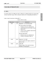
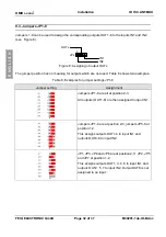
The LEDs, located on the SMA jacks OUT1-8 (LEDout1-8), indicate whether the corresponding
channel is switched or open. When a channel is switched, the corresponding LED will be on.
Table 2 shows the functions of LEDs LED1-3:
Table 2: LED1-3 function
Abbreviation
Color
Description
LED1
red
Diagnostic 1: „Communication-LED“
HF-Communication Control Mode:
-
Flashes on when the multiplexer has
received a signal from the reader through
SMA jack IN1.
-
Comes on when multiplexer has detected
an error at an output.
External Trigger Mode:
-
Flashes on when the multiplexer has
received a valid pulse through X2.
LED2
green
Diagnostic 2: „HF-LED“
Comes on when an HF-signal is present on
SMA jack IN1.
LED3
green
„RUN-LED“:
Flashes (approx. 1Hz) when the internal
software is running properly.


