Wiring the Pathfinder Expansion Module
15
Installation and Maintenance Manual
Federal Signal
www.fedsig.com
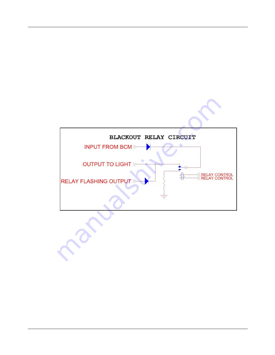
Blackout Relay Circuit
When the Expansion Module is installed, the signal from the Body Control Module
(BCM) is brought into the module and travels through a diode. The signal is then
applied to the pole of a Single Pole Double Throw (SPDT) relay. The Normally
Closed (NC) contact passes the signal to the output to the light. The flashing output
is connected to the output to the light through a diode.
During normal operation, the tail/brake/reverse light turns on when either the
Body Control Module applies a signal to the light or the flashing signal turns on. A
convergence command can be issued to “black out” the output to the light. When
this command is issued, the relays are switched and the signal from the Body
Control Module are switched to drive a resistive load.
The diodes in the circuit isolate the signals so they do not interfere with each other.
Figure 5 Circuit
Relay 1 - 16 = 7.5 A Maximum
Relay 17 & 18 = 20 A Maximum


