F8
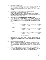
If the room temperature >=31
°
C, compressor off, outdoor fan off and 4-way valve remains
on, indoor fan runs according to following table:
ID Room Temp., Tr
Tr<=31
°
C
31
°
C<Tr<32
°
C
Tr>=32
°
C
ID Fan
SET
*
LOW
*
Maintain current state
The heating cycle starts and stops according to the result of set temperature - room
temperature comparison:
ID Room Temp.
< Set pt-1°C = Set pt-1°C = Set pt.
=Set pt+1°C > Set pt+1°C
Heat Mode Cycle
Start
Start
*
Stop
Stop
*
Maintain current state
The 4-way valve will always be on in this mode except during de-icing, while the indoor fan
will be turned on or off in accordance to cool air prevention requirement.
4.
Auto Mode
Depending on the room temperature, the air-con controller will automatically select cool, dry
or heat mode when this mode is first selected. The selected mode of operation will not be
exited until Auto mode is de-selected. If automatic operation is chosen, auto mode will be
automatically selected.
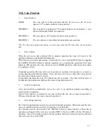
Room Temperature Range
Mode of Operation That Will Be Entered if Auto Mode
Is Selected
Room Temp. >24ºC
Cool Mode
19 ºC
<
Room Temp.
≤
24ºC
Dry Mode
Room Temp.
≤
19ºC
Heat Mode
(Heat Pump Unit only)
Mode selection rule in Auto mode
The set temperature is internally set at 22ºC. In manual operation, the user can change it in
steps of 2ºC to 20ºC or 24ºC by pressing "
∨∨
" or "
∧∧
" button on the hand-held transmitter.
Conversely, this is not possible in automatic operation.
5.
Fan Mode
Only indoor fan and the vane operate in this mode.
The user can select the desired indoor fan speed and vane position, but auto fan speed
selection is not available.
Содержание E1FC418N6G
Страница 1: ...ISSUED ON 1 APRIL 2003 FEDDERS LARGE SPLIT UNIT R407C SERVICE MANUAL ...
Страница 3: ...SECTION A SPECIFICATIONS ...
Страница 5: ...SECTION B PARTS LIST AND EXPLODED VIEWS ...
Страница 10: ......
Страница 11: ......
Страница 12: ......
Страница 16: ......
Страница 17: ......
Страница 18: ......
Страница 19: ......
Страница 20: ...SECTION C INSTALLATION ...
Страница 21: ...SPLIT TYPE AIR CONDITIONER INSTALLATION MANUAL For 18 000 24 000 Btu C1 ...
Страница 39: ...SECTION D TROUBLE SHOOTING ...
Страница 40: ...D1 ...
Страница 42: ...SECTION E WIRING DIAGRAM ...
Страница 43: ...E1 ...
Страница 44: ...E2 ...
Страница 45: ...E3 ...
Страница 46: ...E4 ...
Страница 47: ...SECTION F TECHNICAL DATA ...
Страница 68: ...F21 ...
Страница 69: ...F22 ...
Страница 70: ...F23 ...
Страница 71: ...F24 ...
Страница 72: ...F25 ...
Страница 73: ...F26 ...
Страница 74: ...F27 ...
Страница 75: ...F28 ...


