F14
XI.
Device Protection Measures
1.
3-minutes compressor switch on delay
The compressor is not switched on again for 3-minutes every time after it is switched off to
protect it. This restriction applies throughout the operation of the Air-con except on power-
up.
2.
Cool mode protection (Low-pressure indicator)
If the indoor coil thermistor temperature is 25
°
C and above after the compressor has been
turned on for more than 30 minutes in cool mode only, the compressor stop, outdoor fan stop,
4-way valve off and indoor fan run at low speed and the RED LED will blink at 95 times per
minute.
When compressor is stopping , the microprocessor will not monitoring the indoor coil
thermistor temperature
(applicable on Heat Pump Unit only)
If the outdoor coil thermistor temperature is more than 60
°
C in cool mode, the compressor
stops, the outdoor fan remains on, 4-way valve remains off, indoor fan run at set speed.
If the outdoor coil thermistor temperature later dips to 50
°
C or below in cool mode, the
compressor on, outdoor fan remain on, 4-way valve remain off, indoor fan run at set speed.
3.
Heat mode protection
(applicable on Heat Pump Unit only)
If the indoor coil thermisor temperature is 28
°
C and below after the compressor has been
turned on for more than 30 minutes in heat mode only, then the compressor will stop and the
outdoor fan will stop, the 4-way valve will remain on and the indoor fan stop, the RED LED
will blink at 95 times per minute.
The thermistor accuracy and responses time both are very critical for heat mode indoor coil
overload protection, The software must be able to detect the system rate of change, this
would allow the unit to operate at very exrtrem condition without stopping or tripping the
compressor during the heat mode operation. Details refer to Heat Mode Protection Control
Sequences attached.
4.
On/off Hysteresis
In order to avoid switching the relays and the associated devices too frequently, some
hysteresis is incorporated into the starting and stopping of the operation cycles.
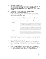
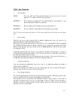
In the
cool, heat and dry modes
, the respective cycles start and stop as shown in the
diagram below:
Room temperature
< Set pt-1°C = Set pt-1°C
= Set pt.
= Set pt+1°C > Set pt+1°C
Cycle
Stop
Stop
*
Start
Start
*
Maintain current state
Содержание E1FC418N6G
Страница 1: ...ISSUED ON 1 APRIL 2003 FEDDERS LARGE SPLIT UNIT R407C SERVICE MANUAL ...
Страница 3: ...SECTION A SPECIFICATIONS ...
Страница 5: ...SECTION B PARTS LIST AND EXPLODED VIEWS ...
Страница 10: ......
Страница 11: ......
Страница 12: ......
Страница 16: ......
Страница 17: ......
Страница 18: ......
Страница 19: ......
Страница 20: ...SECTION C INSTALLATION ...
Страница 21: ...SPLIT TYPE AIR CONDITIONER INSTALLATION MANUAL For 18 000 24 000 Btu C1 ...
Страница 39: ...SECTION D TROUBLE SHOOTING ...
Страница 40: ...D1 ...
Страница 42: ...SECTION E WIRING DIAGRAM ...
Страница 43: ...E1 ...
Страница 44: ...E2 ...
Страница 45: ...E3 ...
Страница 46: ...E4 ...
Страница 47: ...SECTION F TECHNICAL DATA ...
Страница 68: ...F21 ...
Страница 69: ...F22 ...
Страница 70: ...F23 ...
Страница 71: ...F24 ...
Страница 72: ...F25 ...
Страница 73: ...F26 ...
Страница 74: ...F27 ...
Страница 75: ...F28 ...


