F5
c) Filter dirty/System Fault (red)
Lights up after 500 hours of operation, to
LED
indicate that the filter requires cleansing.
The Operation/Filter reset switch should be
pressed by the user to switch this LED
indication off after cleansing and replacing the
filter.
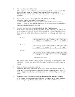
When Indoor air thermistor (TH1) fault. It blinks at
approximately 30 times per minute, only indoor fan is
operating and reset by turning off main power supply.
When Indoor Coil thermistor (TH2) fault. It blinks at
approximately 60 times per minute. The indoor fan is
operating according to the cold air prevention in heat
mode and normal in cool mode and reset by turning off
main power supply.
When outdoor coil thermistor (TH3) fault. It blinks at
approximately 150 times per minute. The indoor fan is
operating according to the cold air prevention in heat
mode and normal in cool mode and reset by turning off
main power supply. In case the thermistor is fault, the
transimitter will not be able to function
(applicable on
Heat Pump Unit only).
Check thermistor open or short circuit.
3.
Infra Red Sensor Board
An Infra-Red sensor on this board detects infra-fed signal transmission from the remote hand
held transmitter.
IV.
Operations of the electronic controller
1.
ON
In manual operation, the air-con is switched on when ON/OFF button of the hand held
transmitter is pressed while the air-con is off.
For automatic operation, the air-con is switched on if the push botton is pressed once.
The microprocessor will regulate room temperature automatically.
2.
OFF
In manual operation, the air-con is switched off once the ON/OFF button is pressed
again or when the operation push button is pressed two times.
When the air-con is turned off, it does not regulate the indoor temperature.
The vane motor will execute a final sequence of movement to the HOME position,
causing the air flow outlet to be fully closed.
Содержание E1FC418N6G
Страница 1: ...ISSUED ON 1 APRIL 2003 FEDDERS LARGE SPLIT UNIT R407C SERVICE MANUAL ...
Страница 3: ...SECTION A SPECIFICATIONS ...
Страница 5: ...SECTION B PARTS LIST AND EXPLODED VIEWS ...
Страница 10: ......
Страница 11: ......
Страница 12: ......
Страница 16: ......
Страница 17: ......
Страница 18: ......
Страница 19: ......
Страница 20: ...SECTION C INSTALLATION ...
Страница 21: ...SPLIT TYPE AIR CONDITIONER INSTALLATION MANUAL For 18 000 24 000 Btu C1 ...
Страница 39: ...SECTION D TROUBLE SHOOTING ...
Страница 40: ...D1 ...
Страница 42: ...SECTION E WIRING DIAGRAM ...
Страница 43: ...E1 ...
Страница 44: ...E2 ...
Страница 45: ...E3 ...
Страница 46: ...E4 ...
Страница 47: ...SECTION F TECHNICAL DATA ...
Страница 68: ...F21 ...
Страница 69: ...F22 ...
Страница 70: ...F23 ...
Страница 71: ...F24 ...
Страница 72: ...F25 ...
Страница 73: ...F26 ...
Страница 74: ...F27 ...
Страница 75: ...F28 ...


