8
MAINTENANCE MANUAL: MODELS 860, LF860, 860U & LF860U
1
/
2
"- 2" (15 – 50mm)
Relief Valve Repair - continued
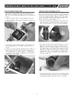
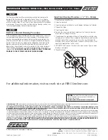
5 . Before installing the new internal relief valve assembly module, apply
a thin coating of supplied lubricant to both sides of one slip ring (Item
18 .1) and insert it into the top of the relief valve cover . Install the new
internal relief valve assembly module by grasping the outside of the
outer diaphragm in one hand and the smaller diaphragm in the other
hand . Then pull upward gently on the small outer diaphragm (Item 16)
so that it forms the shape of a tulip . Hold the small diaphragm so that
it maintains this “tulip” shape while sliding it through the relief valve
cover hole and plastic diaphragm gasket .
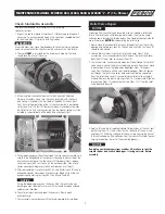
6 . Apply a thin coating of supplied lubricant to both sides of the second
slip ring (Item 18 .1) and place it over the top of the small diaphragm
making sure the outer diaphragm (Item 16) is not folded or creased
under the slip ring . Push the slip ring down flat until the adhesion from
the grease holds the small diaphragm in place . This should roll the
diaphragm as shown . Thread the brass cylinder (Item 18) into the relief
valve cover and hand tighten .
CAUTION
!
Do not twist the internal parts when the cylinder is tightened . The small
diaphragm may become folded or creased if the internal
assembly is restricted while tightening the cylinder .
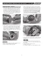
7 . Replace O-ring (Item 20) in relief valve cover . Make sure the round
bead on the large diaphragm is properly seated in the counterbore of
the relief valve cover . Position spring (Item 13) over the seat ring in the
relief valve body and hold in place while inserting the guide end (Item
23) of the relief valve assembly module and relief valve cover . Position
the assembly so the O-ring aligns with the sensing hole in the body
and the guide slides into the seat ring . Replace relief valve cover bolts
and tighten to approximately 35 inch
•
pounds .
Do not over tighten
.
Tighten the brass cylinder (Item 18) in the relief valve cover to approxi-
mately 30 feet pounds of torque .
Do not over tighten
.
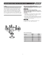
8 . After reassembly, with all test cocks closed, slowly open inlet ball valve
and bleed air from the unit by opening and closing test cock #2, then
#3 and finally #4 .
NOTICE
During the bleeding process, the relief valve may discharge a high
volume of water until all test cocks have been closed and pressure has
been stabilized .
9 . Check for external leaks and repair if necessary .
Slowly open outlet ball valve .
10 . Test assembly in accordance with the locally approved test method .


