7
MAINTENANCE MANUAL: MODELS 860, LF860, 860U & LF860U
1
/
2
"- 2" (15 – 50mm)
Check Module Re-Assembly
Use reverse procedure for assembly with the following
special instructions .
1 . Inspect the check module O-ring (Item 3 .1) for damage and replace if
necessary . To ease assembly, apply a thin coating of supplied lubricant
to the O-ring (Item 3 .1) prior to installing in body .
CAUTION
!
Excess lubricant may cause foreign debris to collect on internal compo-
nents which could foul the check assembly and result in a test failure .
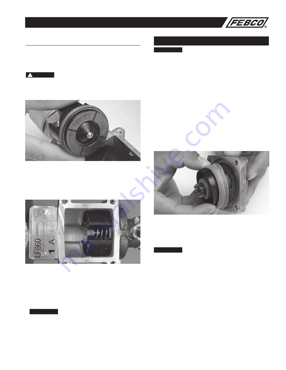
2 . The word
INLET
is inscribed on the end of each module . That end
should face the inlet of the valve .
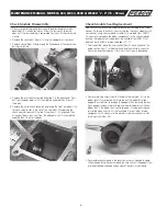
3 . When installing the check modules On the Series 860 Reduced
Pressure Assembly, make sure the check assembly with the heavy
duty spring is inserted in the inlet bore of the body (1st check posi-
tion) . Ensure the orientation of the 1st check assembly is positioned
so that one (1) of the four (4) flow path windows faces down towards
the Relief Valve . The check assembly with the weaker spring must be
installed in the outlet bore of the body (2nd check position) .
4 . When replacing spacer (Item 8) between the two check assemblies, be
sure that the flanged end of the spacer is touching the back side of the
inlet check assembly so that the cover will fit properly . Next, replace
cover making sure #3 test cock is on the upstream side . Do not over
tighten cover bolts (Approximately 35 inch
•
pounds is sufficient) .
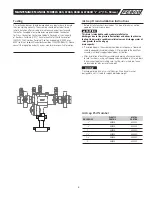
5 . After reassembling, close test cock #2, #3 and #4 (test cock #1 should
already be closed), slowly open inlet ball valve . Bleed air from the unit
by opening and closing test cock #2, then #3 and finally #4 .
NOTICE
During the bleeding process on the Series 860, the relief valve may
discharge a high volume of water until all test cocks have been closed
and pressure stabilized .
6 . Check for external leaks and repair if necessary . Slowly open
outlet ball valve .
7 . Test assembly in accordance with the locally approved test methods .
Relief Valve Repair
NOTICE
Discharge from the relief valve assembly may not indicate a relief valve
failure . The relief valve will discharge water when the mainline check
valves become fouled with foreign debris . See Troubleshooting Guide for
more information
BEFORE
disassembling the relief valve .
1 . Slowly close inlet and outlet ball valves . Bleed off air from the unit by
opening and closing test cock #2, then #3, and finally #4 . Test cock #1
should remain closed .
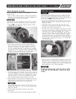
2 . Loosen brass cylinder in center of relief valve cover (Item 18) by
unscrewing
1
/
4
turn (counterclockwise) . Remove the relief valve cover
bolts (Item 21) and relief valve cover (Item 19) .
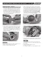
3 . The internal relief valve assembly module will be attached to the relief
valve cover . Unscrew the brass cylinder and remove from cover . Grasp
the outer diameter of the large outer diaphragm (Item 15) and pull
away from the cover until the small outer diaphragm (Item 16) comes
out through the relief valve cover hole and is completely separated
from the relief valve cover . Discard old internal relief valve assembly
module . Remove the plastic slip rings (Item 18 .1) and discard . Slide out
the seat ring (Item 12) and seat gasket ring (Item 12 .1) from the relief
valve body and discard .
4 . Apply a thin coating of supplied lubricant to both sides of the new seat
gasket ring (Item 12 .1), and slide it on the short end of the new seat
ring (Item 12) . Slide the short end of the new seat ring into the hole of
the relief valve body . (The adhesion from the lubricant will hold the seat
ring in place during the rest of the assembly process .)
NOTICE
If applying new diaphragms from a rubber kit, make sure that the
smooth rubber side of each diaphragm, is facing outward. Before
assembly.


