Model ULC Series
06012021ULC,Rev i
Page 10 of 54
4.0 Installation requirements
1. For installation of the Construct on Site chamber and for installation of the refrigeration systems,
please refer to the Installation Manual. If lifting unit, place lift forks under center of enclosure.
2. For proper air flow, ensure there is a minimum of the following distances from the unit to the nearest
wall or ceiling:
Back of unit: 14.0 in. / 35.0 cm
Sides of unit: 14 in. / 35 cm
Top of unit: 12 in./ 30 cm. Overall minimum height of location, floor to ceiling is 13 ft 4 in. / 4.05
meters.
3. Ensure there is 3 feet (1 meter) of free space in front of power supply receptacles.
4. For proper performance, ensure that all product loaded into the chamber is kept at least 1” (2.5
cm) from all wall and ceiling surfaces.
5. Two plugged access port are provided 0.875” (2.22 cm) (see Mechanical Layout drawing for
location). These ports may be used for customer temperature mapping of chamber or continuous
sample monitoring. The port is filled with insulation and both ends are plugged to reduce moisture
infiltration. After monitoring sensors are installed replace the insulation and seal or plug both inside
and outside of the cabinet to reduce moisture infiltration.
Failure to properly seal the access
port on both the interior and exterior will result in moisture infiltration, and performance
degradation of the unit.
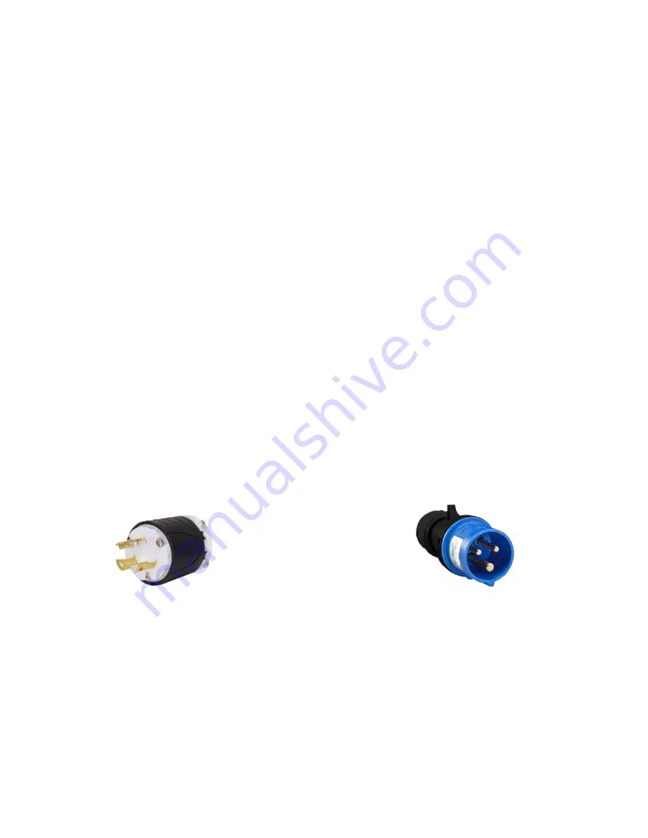
6. Connect each refrigeration system to a separate receptables 30 Amp (32 Amp 50Hz.) 208-230
VAC 2 pole, 2 wires + GND (3 wire receptacle).
Note
: The ULC/ULCi must be powered by 2 separate single phase circuits.
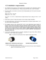
NEMA L6-30P,
LOCKING PLUG (North America)
IEC 60309 Plug (International)
7. Water cooled system (ULC-WC, ULCi-WC).
a. The inlet and outlet water connections are located on the top of each refrigeration
system. The connections are 1/2” FPT.


