


AM-Jackal-2
more quick guides @ www.farmscanag.com/jackal
July 2013
15
Slippage Meter (Wizard)
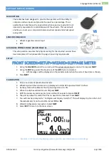
SLIPPAGE METER (WIZARD)
DESCRIPTION
The Jackal has been designed to provide the operator with the ability to
compare and two inputs and provide the result as a percentage. This is
applicable in industries such as agriculture when speed over ground in not
necessarily equivalent to rotational speed of the wheel/s. This wizard will
enable you to set up a comparison between wheel speed and actual speed
(using GPS)
SENSORS REQUIRED
Wheel or gearbox sensor input
GPS
AVAILABLE CONNECTIONS (REFER PAGE 3)
This setup section assumes that physical wiring for the required sensors have
been completed. If not please refer to page 3 on wiring requirements
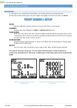
SETUP
FRONT SCREEN>SETUP>WIZARD>SLIPPAGE METER
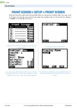
1.
Using the
NAV KEYS
select the current port the wheel sensor input is connect to & press
NEXT
2.
Using the
EDIT
key, select the baud rate of the
GPS
that is connected.
a.
GPS messages will be displayed on the Jackal monitor when the correct baud rate is chosen.
3.
Press
NEXT
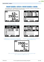
CALIBRATION
1.
Drive at a constant speed above 3km/hr.
2.
Wheel input will then increment up (displayed in Hz) & GPS speed will start to show.
3.
As the system self-calibrates the slip % will get closer to 0%.
4.
When the slip has settled close to 0%press
NEXT
5.
EDIT the necessary alarm points to be notified of any alerts & select
NEXT
6.
The port by default is called “SLIP” & no need to be renamed. Press
NEXT
7.
You will now be prompted to “Configure next display to km/hr?” This will display slip % on the 1st of
the Jackal & km/hr on the 2nd line. Select
YES
or
NO
8.
Wizard Configuration Successful , Select
NEXT
9.
Select
EXIT
to return to the main screen.
Example : 2 UP monitoring slippage versus ground speed displayed as a percentage
VS
Содержание Jackal v2
Страница 1: ......


